DTC P0712 4.8L and 6.0L
Circuit Description
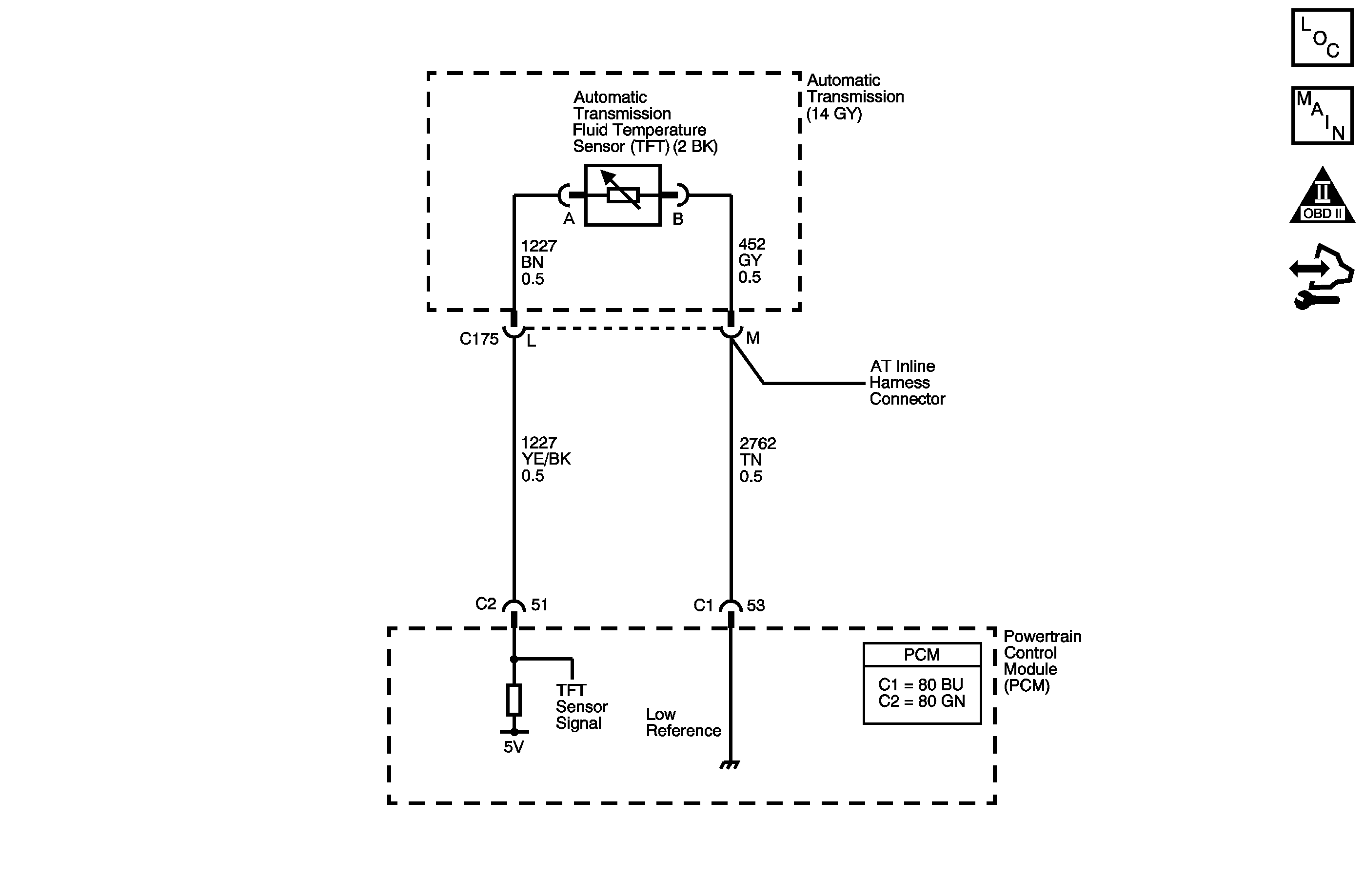
The automatic transmission fluid temperature (TFT) sensor is part of the 4L80-E automatic transmission (AT) wiring harness assembly. The TFT sensor is a resistor, or thermistor, which changes value based on temperature. The sensor has a negative-temperature coefficient. This means that as the temperature increases, the resistance decreases, and as the temperature decreases the resistance increases. The powertrain control module (PCM) supplies a 5-volt reference signal to the sensor and measures the voltage drop in the circuit. When the transmission fluid is cold, the sensor resistance is high and the PCM detects high signal voltage. As the fluid temperature warms to a normal operating temperature, the resistance becomes less and the signal voltage decreases. The PCM uses this information to control shift quality and torque converter clutch (TCC) apply.
If the PCM detects a continuous short to ground in the TFT sensor or signal circuit, then DTC P0712 sets. DTC P0712 is a type C DTC.
DTC Descriptor
This diagnostic procedure supports the following DTC:
DTC P0712 Transmission Fluid Temperature (TFT) Sensor Circuit Low Voltage
Conditions for Running the DTC
| • | No TFT DTC P0713. |
| • | System voltage is 8-18 volts. |
| • | The engine is running for greater than 7 seconds. |
Conditions for Setting the DTC
The TFT sensor indicates a voltage of less than 0.14 volts for 17 seconds.
Action Taken When the DTC Sets
| • | The PCM does not illuminate the malfunction indicator lamp (MIL). |
| • | The PCM commands increased line pressure. |
| • | The PCM freezes transmission adaptive functions. |
| • | The PCM determines a default TFT using the following matrix: |
| - | If the engine run time is less than 60 seconds then default TFT equals 47°C (117°F). |
| - | If ECT is less than 20°C (68°F), then default TFT equals IAT. |
| - | If the ECT is 20-110°C (68-230°F) then default TFT equals ECT. |
| - | If the ECT is greater than 110°C (230°F) then default TFT is set to 140°C (284°F) and transmission shift pattern is in hot mode. |
| - | If ECT and TFT DTCs are both set then default TFT is 140°C (284°F). |
| • | The PCM records the operating conditions when the Conditions for Setting the DTC are met. The PCM stores this information as Failure Records. |
| • | The PCM stores DTC P0712 in PCM history. |
Conditions for Clearing the DTC
| • | A scan tool clears the DTC from PCM history. |
| • | The PCM clears the DTC from PCM history if the vehicle completes 40 warm-up cycles without a non-emission related diagnostic fault occurring. |
| • | The PCM cancels the DTC default actions when the fault no longer exists and the ignition switch is OFF long enough in order to power down the PCM. |
Diagnostic Aids
DTC P0712 defaults to an elevated line pressure condition which may result in partial TCC apply. This may produce an idle surge that could stall the engine.
Test Description
The numbers below refer to the step numbers on the diagnostic table.
-
This step tests for a short to ground or a skewed sensor by verifying the fault still exists.
-
This step tests for an internal fault within the transmission by creating an open.
Step | Action | Value | Yes | No |
|---|---|---|---|---|
1 | Did you perform the Diagnostic System Check - Vehicle? | -- | Go to Step 2 | |
2 | Inspect for correct transmission fluid level. Refer to Transmission Fluid Check . Did you perform the fluid checking procedure? | -- | Go to Step 3 | Go to Transmission Fluid Check |
Important: Before clearing the DTC, use the scan tool in order to record the Failure Records. Using the Clear Info function erases the Failure Records from the PCM. Does the scan tool display a TFT Sensor signal voltage greater than the specified value? | 0.2 V | Go to Testing for Intermittent Conditions and Poor Connections | Go to Step 4 | |
Does the scan tool display a TFT Sensor signal voltage greater than the specified value? | 4.92 V | Go to Step 5 | Go to Step 6 | |
5 |
Does the resistance measure within the specified range? | 3,088-3,942 ohms at 20°C (68°F) 159-198 ohms at 100°C (212°F) | Go to Testing for Intermittent Conditions and Poor Connections | Go to Step 7 |
6 | Test the signal circuit of the TFT sensor signal circuit for a short to ground between the PCM connector C2 and the AT inline 20-way connector. Refer to Testing for Short to Ground and Wiring Repairs . Did you find and correct the condition? | -- | Go to Step 9 | Go to Step 8 |
7 | Replace the AT wiring harness assembly. Refer to Valve Body and Pressure Switch Replacement . Did you complete the replacement? | -- | Go to Step 9 | -- |
8 | Replace the PCM. Refer to Control Module References for replacement, setup, and programming. Did you complete the replacement? | -- | Go to Step 9 | -- |
9 | Perform the following procedure in order to verify the repair:
Has the test run and passed? | -- | Go to Step 10 | Go to Step 2 |
10 | With the scan tool, observe the stored information, capture info and DTC info. Does the scan tool display any DTCs that you have not diagnosed? | -- | System OK |
DTC P0712 6.6L
Circuit Description
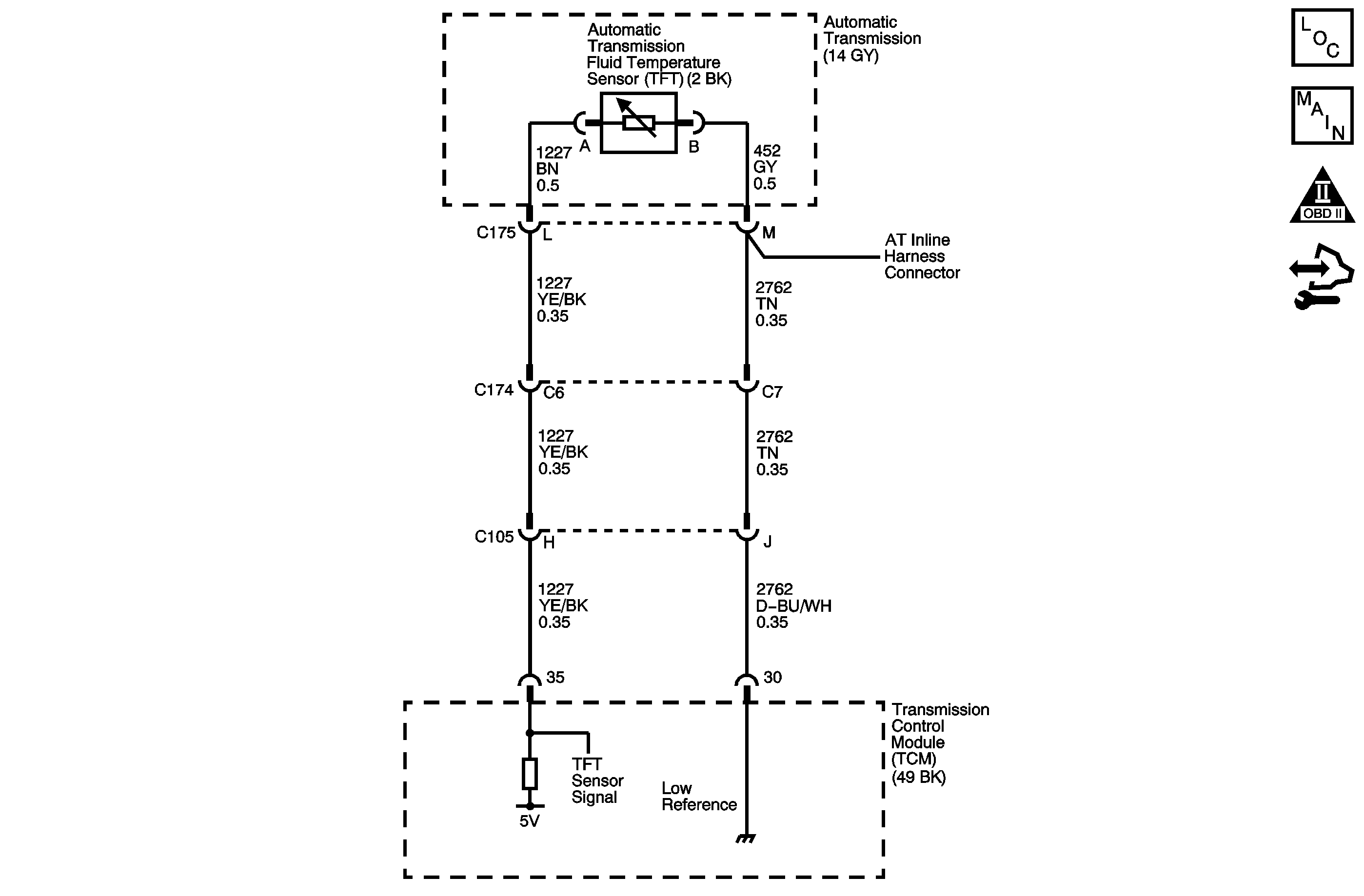
The automatic transmission fluid temperature (TFT) sensor is part of the 4L80-E automatic transmission (AT) wiring harness assembly. The TFT sensor is a resistor, or thermistor, which changes value based on temperature. The sensor has a negative-temperature coefficient. This means that as the temperature increases, the resistance decreases, and as the temperature decreases the resistance increases. The transmission control module (TCM) supplies a 5-volt reference signal to the sensor and measures the voltage drop in the circuit. When the transmission fluid is cold, the sensor resistance is high and the TCM detects high signal voltage. As the fluid temperature warms to a normal operating temperature, the resistance becomes less and the signal voltage decreases. The TCM uses this information to control shift quality and torque converter clutch (TCC) apply.
If the TCM detects a continuous short to ground in the TFT sensor or signal circuit, then DTC P0712 sets. DTC P0712 is a type C DTC.
DTC Descriptor
This diagnostic procedure supports the following DTC:
DTC P0712 Transmission Fluid Temperature (TFT) Sensor Circuit Low Voltage
Conditions for Running the DTC
| • | System voltage is 8-18 volts. |
| • | The engine is running for greater than 5 seconds. |
Conditions for Setting the DTC
The TFT sensor indicates a temperature of 150°C (302°F) or greater for 12 seconds.
Action Taken When the DTC Sets
| • | The TCM does not request the engine control module (ECM) to illuminate the malfunction indicator lamp (MIL). |
| • | The TCM commands increased line pressure. |
| • | The TCM freezes transmission adaptive functions. |
| • | The TCM determines a default TFT using the following matrix: |
| - | If the engine run time is less than 60 seconds then default TFT equals 47°C (117°F). |
| - | If ECT is less than 20°C (68°F), then default TFT equals IAT. |
| - | If the ECT is 20-110°C (68-230°F) then default TFT equals ECT. |
| - | If ECT and TFT DTCs are both set then default TFT is 140°C (284°F). |
| • | The TCM records the operating conditions when the Conditions for Setting the DTC are met. The TCM stores this information as Failure Records. |
| • | The TCM stores DTC P0712 in TCM history. |
Conditions for Clearing the DTC
| • | A scan tool clears the DTC from TCM history. |
| • | The TCM clears the DTC from TCM history if the vehicle completes 40 warm-up cycles without a non-emission related diagnostic fault occurring. |
| • | The TCM cancels the DTC default actions when the fault no longer exists and the DTC passes. |
Diagnostic Aids
DTC P0712 defaults to an elevated line pressure condition which may result in partial TCC apply. This may produce an idle surge that could stall the engine.
Test Description
The numbers below refer to the step numbers on the diagnostic table.
-
A value greater than 150°C (302°F) indicates the fault is present. A value below 150°C (302°F) indicates the fault is intermittent.
-
A value less than -40°C (-40°F) indicates the fault is in the transmission side.
-
For resistance at other temperatures, refer to Transmission Fluid Temperature Sensor Specifications .
Step | Action | Value | Yes | No | ||||
|---|---|---|---|---|---|---|---|---|
1 | Did you perform the Diagnostic System Check - Vehicle? | -- | Go to Step 2 | |||||
Important: Before clearing the DTCs, use the scan tool in order to record the ECM and TCM Failure Records. Using the Clear Info function erases the Failure Records from the ECM and TCM. Does the scan tool indicate that the TFT is greater than the specified value? | 150°C (302°F) | Go to Step 3 | Go to Testing for Intermittent Conditions and Poor Connections | |||||
Does the scan tool indicate that the TFT is less than the specified value? | -40°C (-40°F) | Go to Step 5 | Go to Step 4 | |||||
4 | Test the signal circuit of the TFT sensor for a short to ground between the TCM and the AT inline 20-way connector. Refer to Testing for Short to Ground and Wiring Repairs . Did you find and correct the condition? | -- | Go to Step 11 | Go to Step 10 | ||||
Does the resistance measure within the range specified for the given transmission temperatures? | 3,164-3,867 ohms @ 20°C (68°F) 225-285 ohms @ 88°C (190°F) | Go to Step 6 | Go to Step 7 | |||||
6 | Test the signal circuit of the TFT sensor for a short to ground between the AT inline 20-way connector and the TFT sensor. Refer to Testing for Short to Ground . Did you find the condition? | -- | Go to Step 9 | Go to Testing for Intermittent Conditions and Poor Connections | ||||
7 |
Did you find the condition? | -- | Go to Step 9 | Go to Step 8 | ||||
8 | Replace the TFT sensor. Refer to Valve Body and Pressure Switch Replacement . Did you complete the replacement? | -- | Go to Step 11 | -- | ||||
9 | Replace the automatic transmission wiring harness. Refer to Valve Body and Pressure Switch Replacement . Did you complete the replacement? | -- | Go to Step 11 | -- | ||||
10 | Replace the TCM. Refer to Control Module References for replacement, setup, and programming. Did you complete the replacement? | -- | Go to Step 11 | -- | ||||
11 | Perform the following procedure in order to verify the repair:
Has the test run and passed? | -- | Go to Step 12 | Go to Step 2 | ||||
12 | With the scan tool, observe the stored information, capture info and DTC info. Does the scan tool display any DTCs that you have not diagnosed? | -- | System OK |
