For 1990-2009 cars only
Special Tools
J 23523-F Balancer Remover and Installer
For equivalent regional tools, refer to Special Tools.
- Look to ensure that the crankshaft balancer front groove pin is installed in the proper location, if applicable.
- Apply a small amount of adhesive GM P/N 12346141 (Canadian P/N 10953433) or equivalent, onto the crankshaft balancer keyway in order to seal the crankshaft balancer keyway and crankshaft joint.
- Align the keyway of the crankshaft balancer with the crankshaft balancer key.
- Install the crankshaft balancer onto the end of the crankshaft.
- Use the J 23523-F installer in order to press the crankshaft balancer onto the crankshaft.
- Remove the J 23523-F installer .
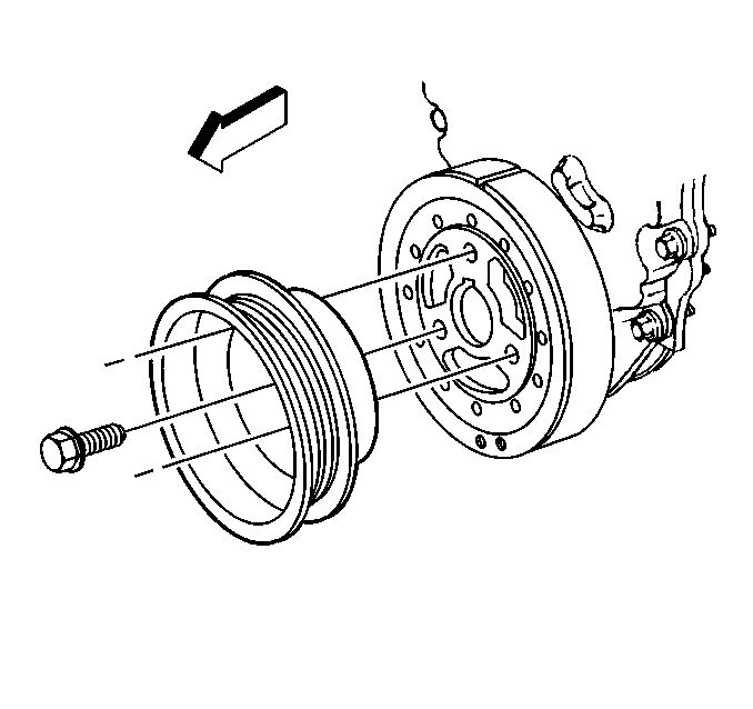
- Install the crankshaft pulley and bolts. Finger tighten all bolts until snug. Tighten the crankshaft pulley bolts to 58 N·m (43 lb ft).
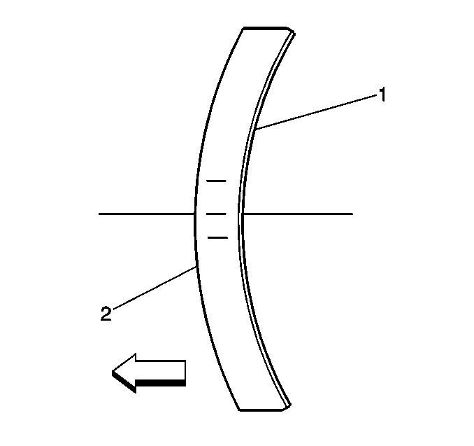
- Ensure that the crown of the crankshaft balancer washer (2) is faced away from the engine.
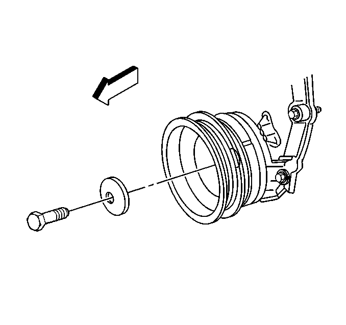
- Install the crankshaft balancer washer and the bolt and tighten to 95 N·m (70 lb ft).
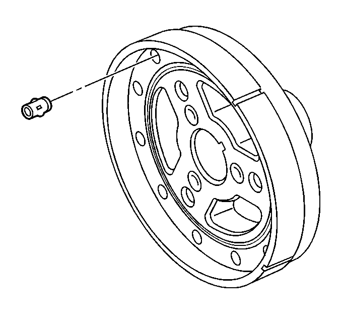
The length and location of the pins must be the same as the original length and location.
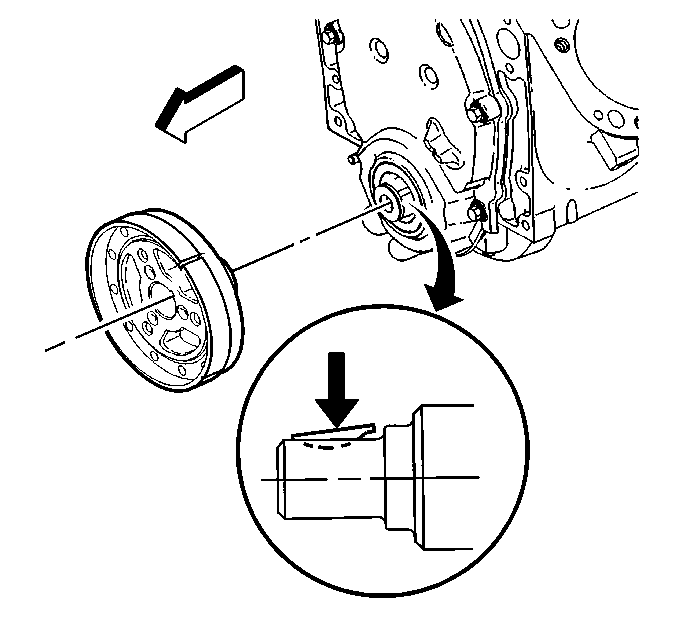
Caution: The inertial weight section of the crankshaft balancer is assembled to the hub with a rubber type material. The correct installation procedures (with the proper tool) must be followed or movement of the inertial weight section of the hub will destroy the tuning of the crankshaft balancer.
Caution: Refer to Fastener Caution in the Preface section.
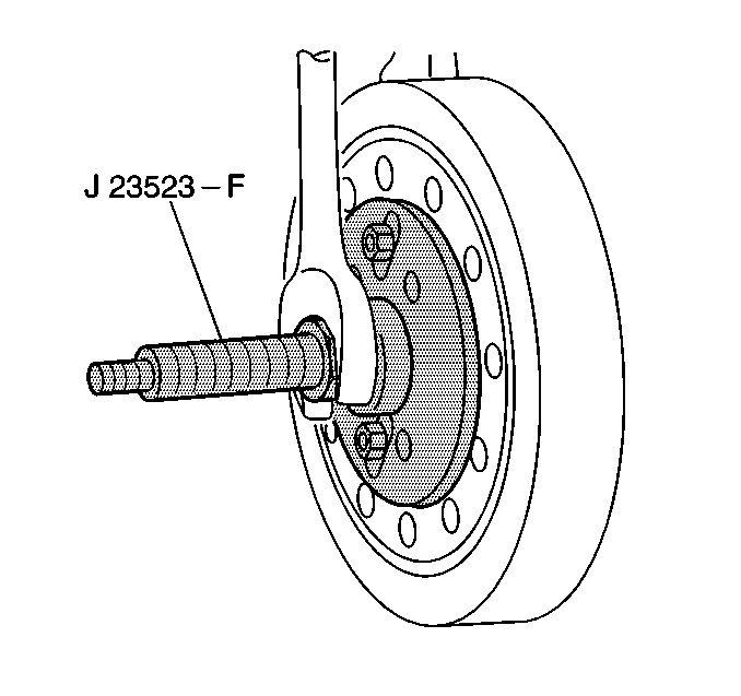
| 5.1. | Install the J 23523-F installer plate and bolts onto the front of the crankshaft balancer. Tighten the J 23523-F installer plate bolts to 25 N·m (18 lb ft). |
| 5.2. | Install the J 23523-F installer screw into the end for the crankshaft. |
| 5.3. | Install the J 23523-F installer bearing, the washer, and the nut onto the J 23523-F installer screw. |
| 5.4. | Rotate the J 23523-F installer nut clockwise until the crankshaft balancer hub is completely seated against the crankshaft position sensor reluctor ring. |
