For 1990-2009 cars only
Intake Manifold Tube Replacement LMM
Removal Procedure
- Disconnect the negative battery cable. Refer to Battery Negative Cable Disconnection and Connection.
- Remove the air cleaner outlet duct. Refer to Air Cleaner Outlet Duct Replacement.
- Remove the engine cover. Refer to Engine Cover Replacement.
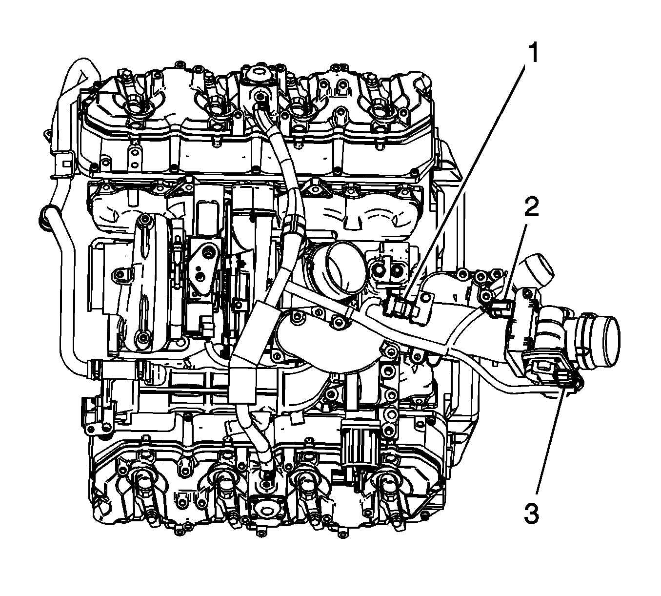
- Disconnect the engine harness electrical connector (1) from the manifold absolute pressure (MAP) sensor.
- Disconnect the engine harness electrical connector (2) from the intake air heater (IAH).
- Disconnect the engine harness electrical connector (3) from the intake air valve.
- Remove the front intake manifold tube nut.
- Reposition the positive battery cable boot.
- Remove the positive battery cable nut at the IAH.
- Remove the positive battery cable from the IAH stud.
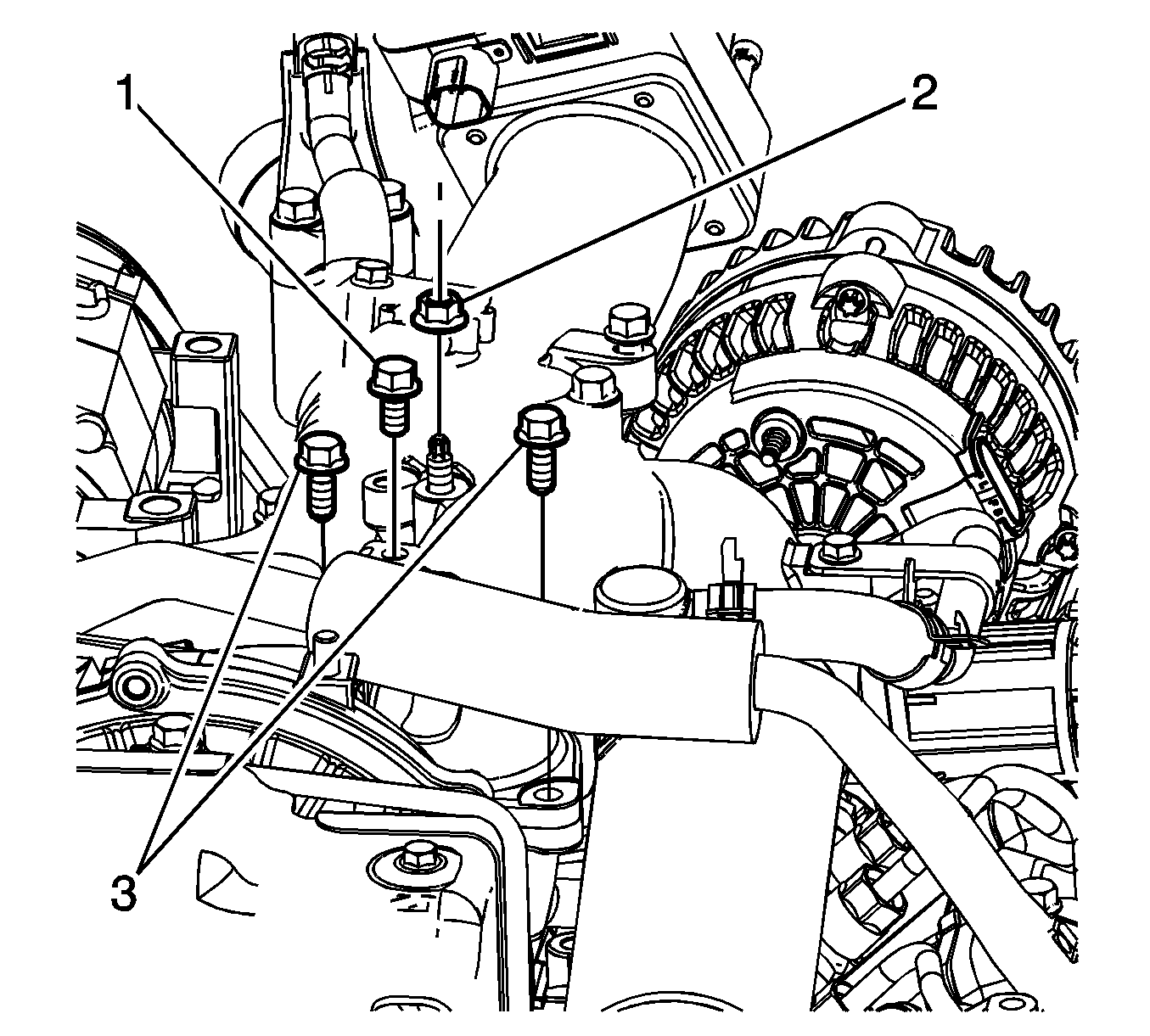
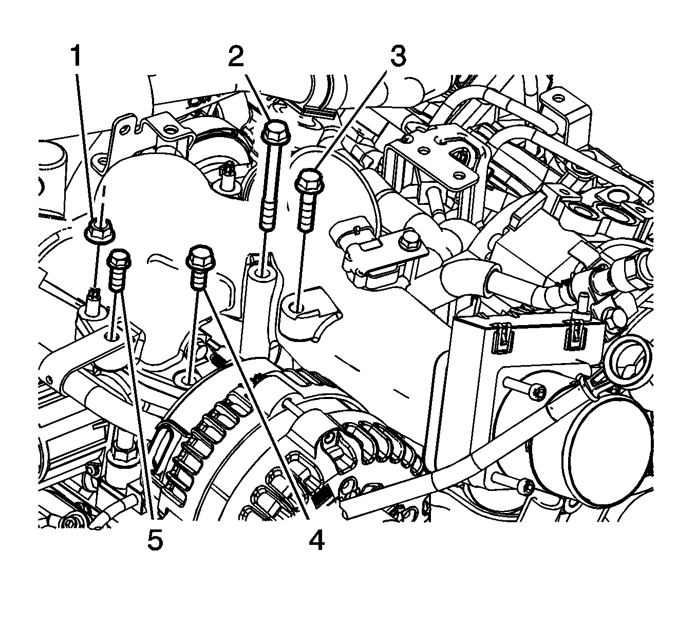
- Remove the engine wiring harness clip bolt (1) at the rear of the intake manifold tube.
- Remove the 2 rear intake manifold tube bolts (3).
- Remove the rear intake manifold tube nut (2).
- Remove the engine wiring harness clip from the intake manifold tube.
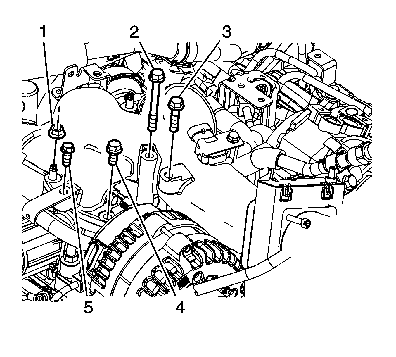
- Remove the engine wiring harness clip bolt (3).
- Remove the intake manifold tube bolts (2, 4) and nut (1).
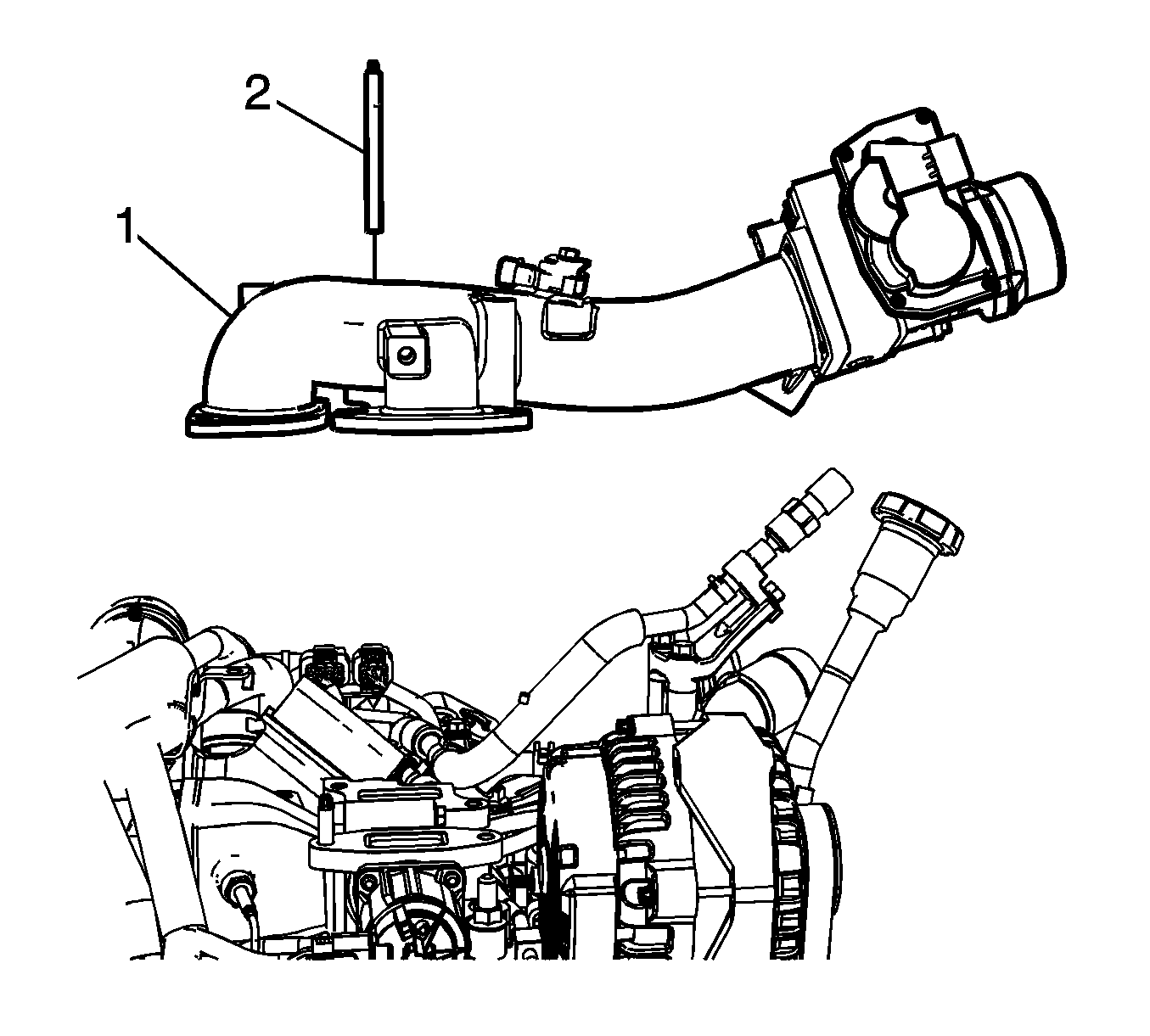
- Remove the intake manifold tube with the stud.
- Remove and discard the 2 metal EGR gaskets from the EGR valve.
- Remove and discard the O-ring seal from the center intake manifold.
- If replacing the intake manifold tube perform the following steps, otherwise proceed to step 5 in the installation procedure.
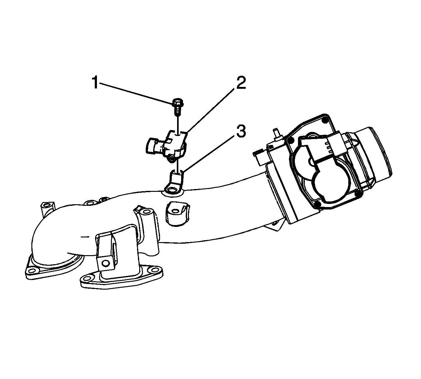
- Remove the MAP sensor bolt.
- Remove the MAP sensor and bracket.
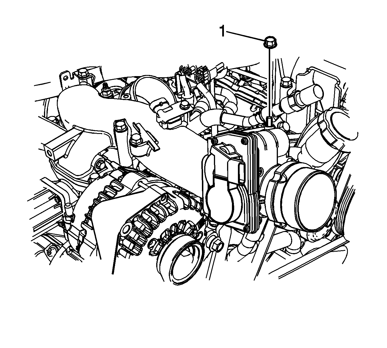
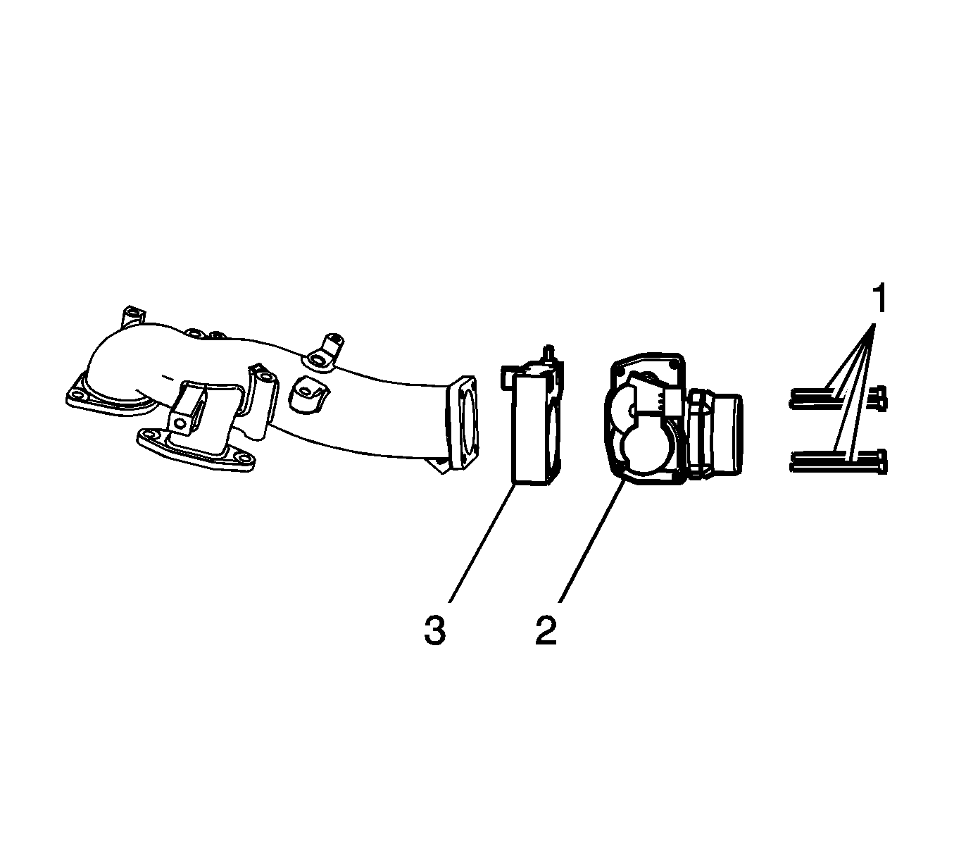
- Remove the air intake valve bolts (1).
- Remove the air intake valve (2) and the IAH (3) from the intake manifold tube.
Installation Procedure
- Position the IAH (3) and the air intake valve (2) to the intake manifold tube.
- Install the air intake valve bolts and tighten to 20 N·m (15 lb ft).
- Install the MAP sensor and bracket.
- Install the MAP sensor bolt and tighten to 10 N·m (89 lb in).
- Install a NEW the O-ring seal onto the center intake manifold.
- Install NEW metal EGR gaskets onto the EGR valve.
- Install the intake manifold tube with the stud and tighten to 25 N·m (18 lb ft).
- Install the intake manifold tube bolts (2, 4) and nut (1) and tighten to 25 N·m (18 lb ft).
- Install the engine wiring harness clip bolt (3) and tighten to 15 N·m (11 lb ft).
- Install the engine wiring harness clip to the intake manifold tube.
- Install the rear intake manifold tube nut (2) and tighten to 25 N·m (18 lb ft).
- Install the 2 rear intake manifold tube bolts (3) and tighten to 25 N·m (18 lb ft).
- Install the engine wiring harness clip bolt (1) at the rear of the intake manifold tube and tighten to 15 N·m (11 lb ft).
- Install the positive battery cable to the IAH stud.
- Install the positive battery cable nut at the IAH and tighten to 10 N·m (89 lb ft).
- Position the positive battery cable boot.
- Install the front intake manifold tube nut. Tighten the bolt to 15 N·m (11 lb ft).
- Connect the engine harness electrical connector (3) to the intake air valve.
- Connect the engine harness electrical connector (2) to the IAH.
- Connect the engine harness electrical connector (1) to the MAP sensor.
- Install the engine cover. Refer to Engine Cover Replacement.
- Install the air cleaner outlet duct. Refer to Air Cleaner Outlet Duct Replacement.
- Connect the negative battery cable. Refer to Battery Negative Cable Disconnection and Connection.

Caution: Refer to Fastener Caution in the Preface section.


