Special Tools
Removal Procedure
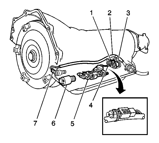
- Ensure that removal of the valve body is necessary before proceeding.
| | Note: The following components can be serviced without removing the valve body from the transmission:
|
| • | The internal wiring harness (2) |
| • | The 1-2 shift solenoid (3) |
| • | The transmission fluid temperature sensor (4) |
| • | The transmission fluid pressure manual valve position switch (5) |
| • | The pressure control solenoid (6) |
| • | The torque converter clutch pulse width modulation (TCC PWM) solenoid (7) |
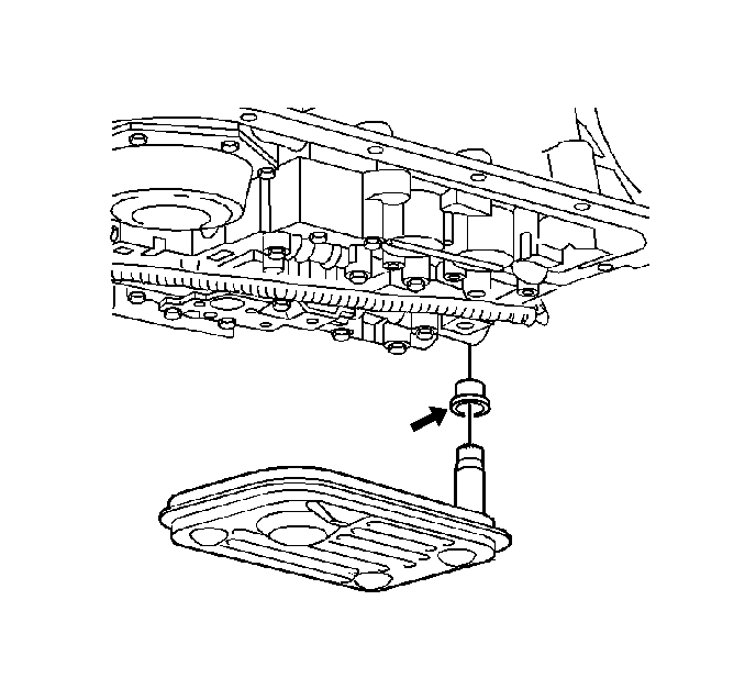
- Remove the fluid level indicator.
- Raise the vehicle. Refer to
Lifting and Jacking the Vehicle.
- Remove the oil pan, gasket, and filter. Refer to
Automatic Transmission Fluid and Filter Replacement.
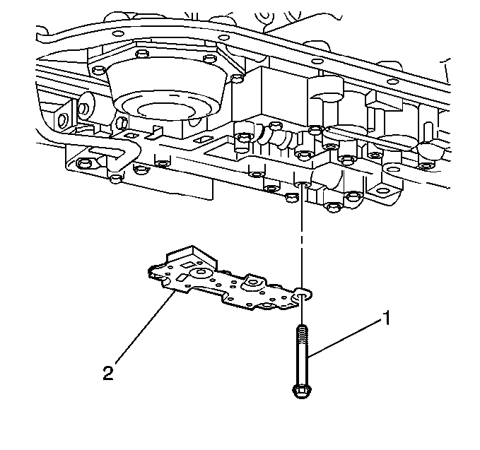
- Disconnect the internal wire harness from the transmission fluid pressure (TFP) manual valve position switch.
Note: Use care not to loose the 5 O-rings that are located between the TFP manual valve position switch and the valve body.
- Remove the control valve body bolts (1) that retain the (TFP) manual valve position switch (2) to the control valve body.
- Remove the TFP manual valve position switch.
- Disconnect the internal wiring harness electrical connectors from the remaining valve body electrical components.
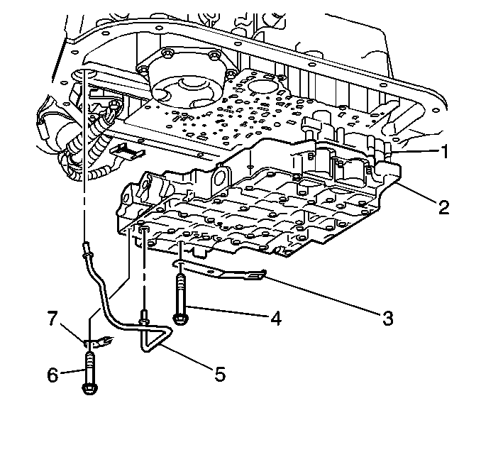
- Remove the lube oil pipe bolt (6) and retainer (7).
- Remove the lube oil pipe (5).
- Remove the bolts and remove the manual shaft detent spring (3).
Note: Keep the control valve body level when lowering it from the vehicle. This will prevent the loss of checkballs located in the transmission case passages.
- Remove the remaining control valve body bolts.
- Carefully lower the valve body down from the transmission case. Use care not to drop the manual shaft valve.
- Remove the control valve assembly (2) which includes the following:
| • | The accumulator housing assembly (1) |
| • | The control valve assembly to the spacer plate gasket |
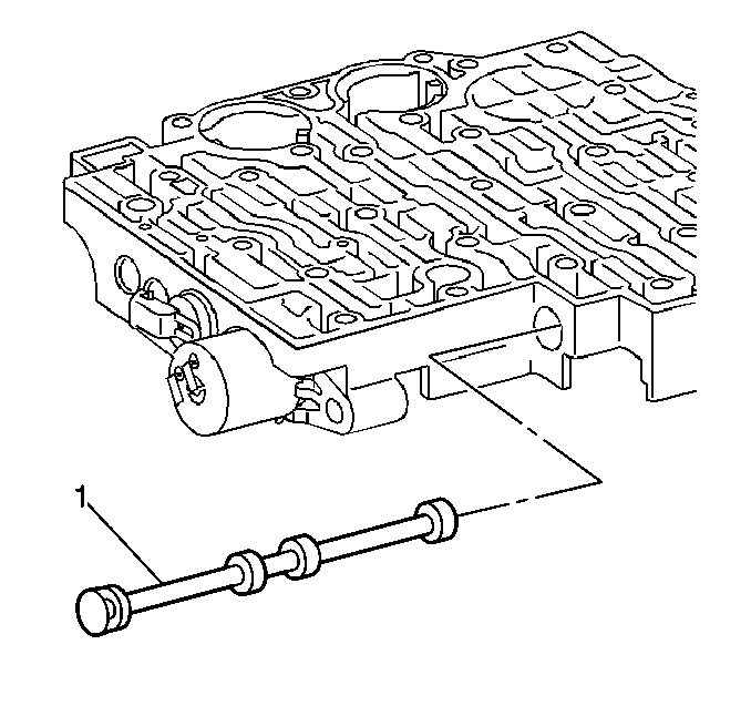
- Remove the manual valve (1) from the control valve body.
- Inspect the manual valve for nicks and burrs.
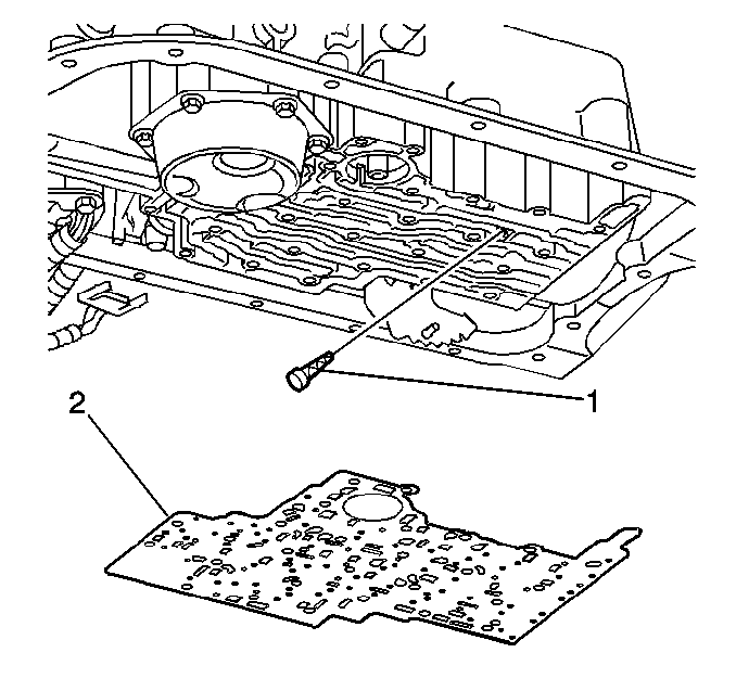
- Remove the spacer plate to case gasket (2) from the case. The gasket may stick to the spacer plate.
- Remove the PWM screen (1) from the case passage.
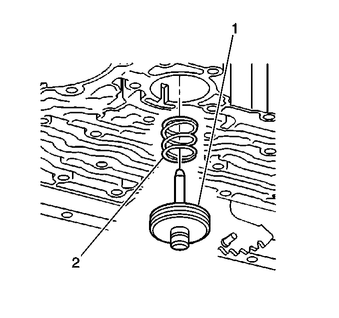
- Remove the manual 2-1 band servo assembly (1).
- Remove the servo piston cushion spring (2).
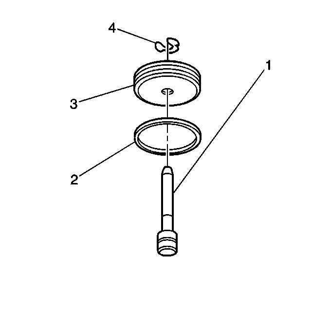
- Remove the manual 2-1 band servo piston pin retainer ring (4).
- Remove the manual 2-1 band servo piston pin (1).
- Remove the manual 2-1 band servo piston seal (2).
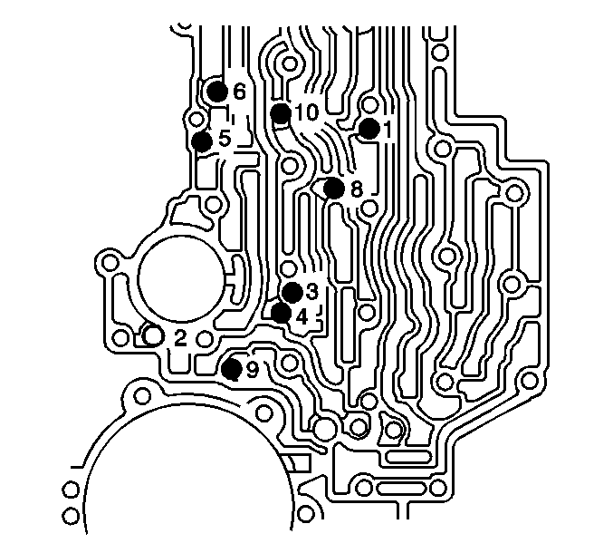
Note: Do not use a magnet in order to remove the checkballs. Using a magnet to remove the checkballs may magnetize the checkballs, causing metal particles to stick.
- Remove the eight checkballs (nine checkballs for some models).
Installation Procedure
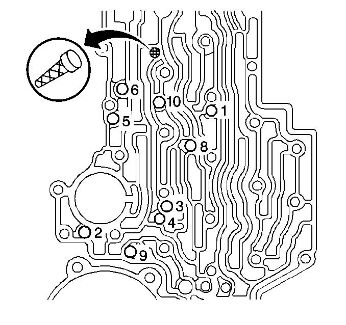
- Install the 8 checkballs (9 checkballs for some models) into the control valve body.
| • | The checkball marked as number 2, is used on RCP, RDP, ZJP and ZLP models only |
| • | To hold the checkballs in place, use the
J 36850 . |
- Install the PWM screen into the control valve body.

- Install a new manual 2-1 band servo piston seal (2) onto the manual 2-1 band servo piston (3).
- Install the manual 2-1 band servo piston pin (1) into the manual 2-1 band servo piston (3).
- Install the manual 2-1 band servo piston pin retainer ring (4).

- Install the manual 2-1 band servo piston cushion spring (2).
Note: Make certain that the tapered end of the manual 2-1 band servo piston pin contacts the manual 2-1 band.
- Install the manual 2-1 band servo piston assembly (1).

- Install the manual valve (1) into the control valve body.
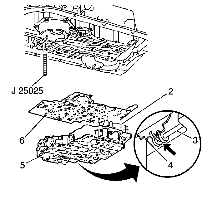
- To aid in alignment and assembly, install tool
J 25025 .
- Install the control valve body gasket (6).
- Install the control valve body assembly (5). Attach the manual valve to the detent lever while installing the control valve body assembly.
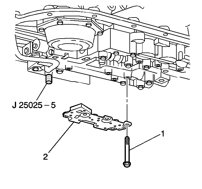
- Install the transmission fluid pressure manual valve position switch (2).
- Install the transmission fluid pressure manual valve position switch bolts (1) finger tight.
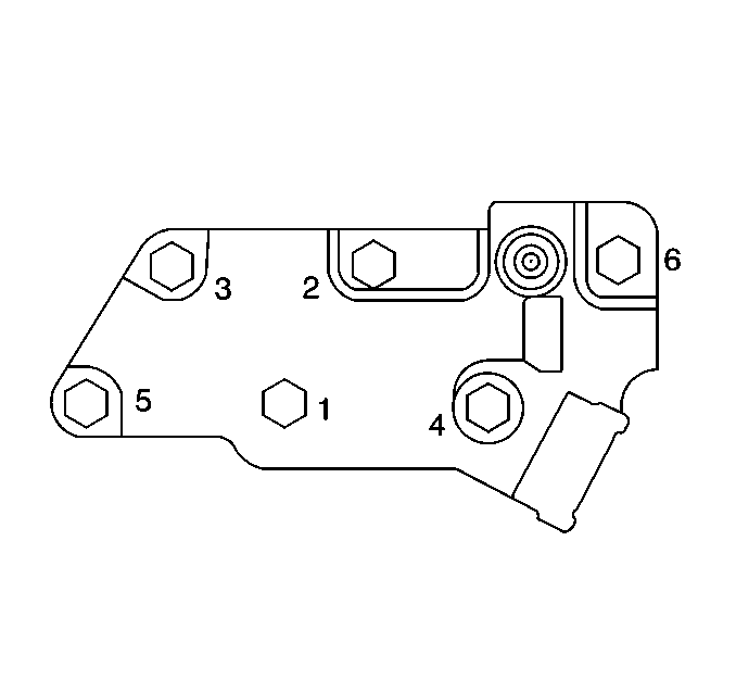
- Tighten the bolts in the order shown to 11 N·m (97 lb in).
- Remove the
J 25025 .
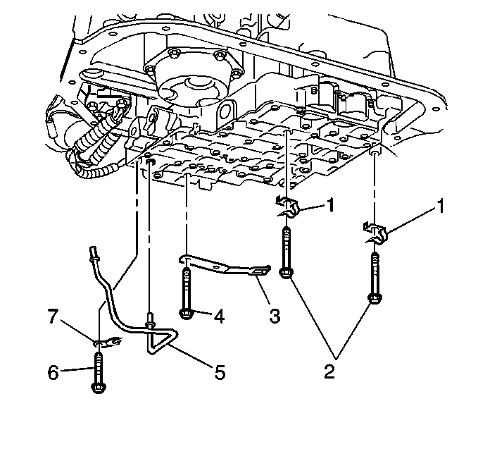
- Install the manual shaft detent roller and spring assembly (3) and bolts.
- Install the two wiring harness clips (1) and bolts (2).
- Install the wiring harness clip (1) and bolts (2).
- Install the lube oil pipe (5) with the short end into the control valve body.
- Install the lube oil pipe retainer (7) and the bolt (6).
Caution: Refer to Fastener Caution in the Preface section.
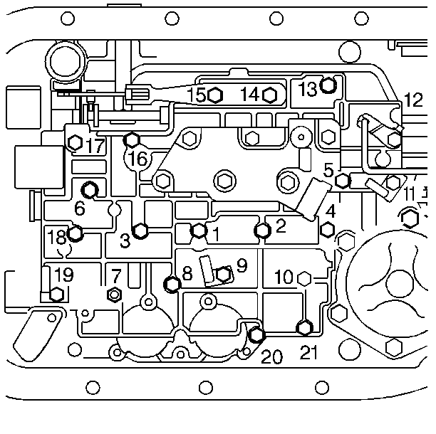
- Install the control valve body bolts and tighten in the order shown to
11 N·m (97 lb in).
- Install the remaining control valve body bolts and tighten to
11 N·m (97 lb in).
- Connect the internal wiring harness to the valve body electrical components.
- Install the oil pan, gasket, and filter. Refer to
Automatic Transmission Fluid and Filter Replacement.
- Lower the vehicle.
- Fill the transmission to the proper level using approved fluid.
- Fill the transmission to the proper level with DEXRON® VI transmission fluid. Refer to
Transmission Fluid Check.
Note: It is recommended that transmission adaptive pressure (TAP) information be reset.
Resetting the TAP values using a scan tool will erase all learned values in all cells. As a result, The ECM, PCM or TCM will need to
relearn TAP values. Transmission performance may be affected as new TAP values are learned.
- Reset the TAP values. Refer to
Transmission Adaptive Functions.


