For 1990-2009 cars only
Special Tools
| • | J 8001 Dial Indicator Set |
| • | J 25025-B Dial Indicator Post and Guide Pin Set |
| • | J 28585 Snap Ring Remover |
For equivalent regional tools, refer to Special Tools.
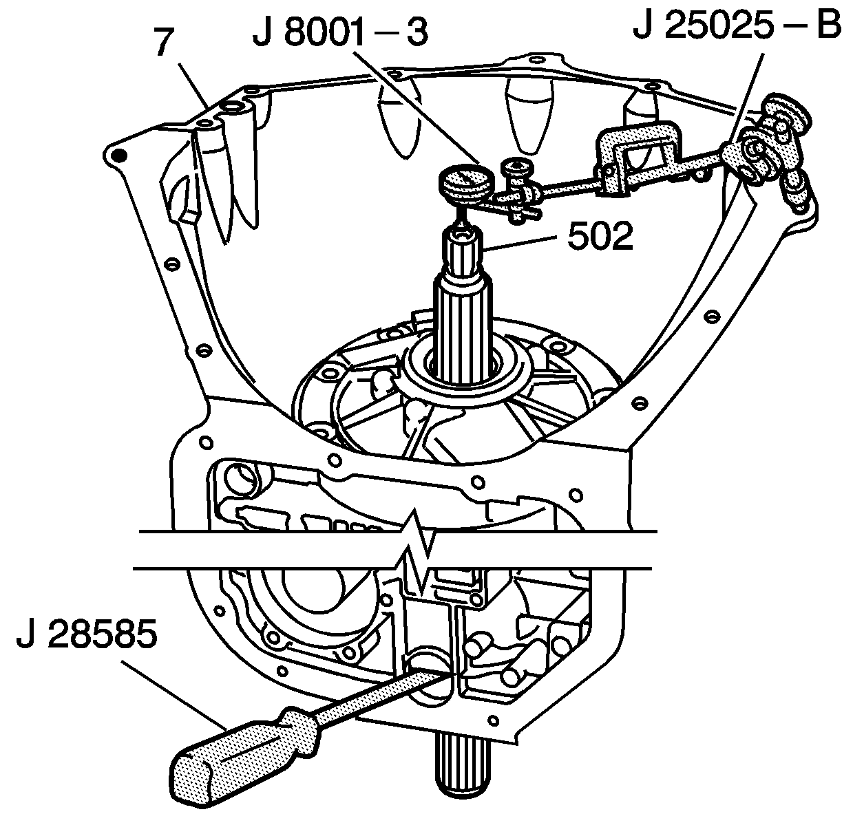
- Assemble the J 25025-B post and guide pin set by attaching the threaded rod and the dial indicator holder to one of the bolt holes on the transmission case assembly (7).
- Assemble the J 8001-3 dial indicator onto the dial indicator holder. Index the J 8001-3 dial indicator to the end of the turbine shaft (502).
- Eliminate any slack by pressing down on the turbine shaft (502).
- Using J 28585 snap ring remover , apply upward pressure on the output carrier assembly to remove free play in the retainer ring.
- Set the J 8001-3 dial indicator to 0.
- Pull up on the turbine shaft (502) while holding up the output carrier assembly with the J 28585 snap ring remover . The correct end play is 0.102-0.559 mm (0.004-0.022 in).
- Remove the tools from the transmission.
- If the front end play measurement is incorrect, refer to the Overrun Clutch Housing Selective Thrust Washer Specifications. Choose a new selective thrust washer based on the original selective washer and the information contained in the table.
- Correct the end play by changing the overrun clutch housing selective thrust washer.

Caution: If the front end play check procedures are not closely followed, you may select an incorrect selective thrust washer thickness. This could result in severe damage to the internal transmission components.
