For 1990-2009 cars only
Removal Procedure
- Disconnect the battery negative cable(s). Refer to Battery Negative Cable Disconnection and Connection.
- Disable the SIR system. Refer to SIR Disabling and Enabling.
- Remove the drivers knee bolster. Refer to Driver Knee Bolster Replacement.
- Remove the drivers knee bolster bracket. Refer to Driver Knee Bolster Bracket Replacement.
- Remove the instrument panel (I/P) cluster trim plate bezel. Refer to Instrument Panel Cluster Trim Plate Bezel Replacement.
- Remove the instrument cluster assembly. Refer to Instrument Cluster Replacement.
- Remove the steering column. Refer to Steering Column Replacement.
- Remove the left hinge pillar trim panel. Refer to Body Hinge Pillar Trim Panel Replacement.
- Remove the right hinge pillar trim panel. Refer to Body Hinge Pillar Trim Panel Replacement.
- Remove the passenger knee bolster. Refer to Passenger Knee Bolster Replacement.
- Remove the passenger knee bolster bracket. Refer to Passenger Knee Bolster Bracket Replacement.
- Remove the body control module (BCM). Refer to Body Control Module Replacement.
- Remove the I/P upper trim pad. Refer to Instrument Panel Upper Trim Pad Replacement.
- Remove the instrument panel SIR module. Refer to Inflatable Restraint Instrument Panel Module Replacement.
- Remove the engine cover. Refer to Engine Cover Replacement.
- Remove the radio. Refer to Radio Replacement.
- Remove the heater and the A/C control. Refer to Heater and Air Conditioning Control Replacement.
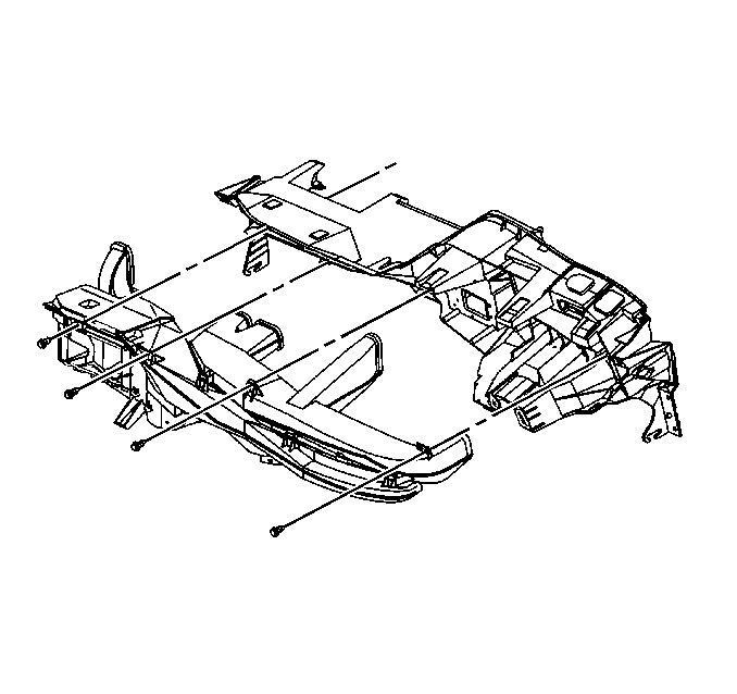
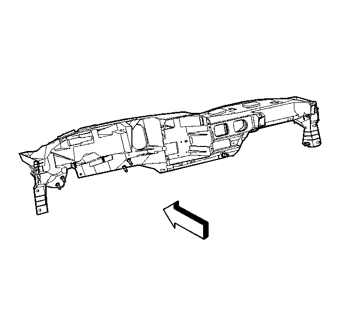
- Remove the bolts that retain the I/P carrier to the vehicle.
- Rotate the I/P carrier out and downward in order to gain access to the HVAC ducts and the electrical harness.
- Remove the bolts that retain the air ducts to the I/P carrier.
- Remove the HVAC air distribution duct from the I/P carrier. Refer to Air Distributor Duct Replacement.
- Note the location and positioning of the Instrument Panel Wiring harness.
- Remove the wiring harness from the I/P carrier.
- Remove the I/P carrier from the vehicle.
Warning: Refer to SIR Warning in the Preface section.
Warning: Refer to Battery Disconnect Warning in the Preface section.


Installation Procedure
- Position the I/P carrier to the vehicle.
- Install the wiring harness to the I/P carrier as noted in the removal procedure.
- Install the HVAC air distribution duct to the I/P carrier. Refer to Air Distributor Duct Replacement.
- Carefully rotate the I/P carrier up and install the additional components.
- Install the bolts that retain the I/P carrier to the vehicle and tighten to 50 N·m (37 lb ft).
- Install the heater and the A/C control. Refer to Heater and Air Conditioning Control Replacement.
- Install the radio. Refer to Radio Replacement.
- Install the engine cover. Refer to Engine Cover Replacement.
- Install the instrument panel SIR module. Refer to Inflatable Restraint Instrument Panel Module Replacement.
- Install the I/P upper trim pad. Refer to Instrument Panel Upper Trim Pad Replacement.
- Install the BCM. Refer to Body Control Module Replacement.
- Install the passenger knee bolster bracket. Refer to Passenger Knee Bolster Bracket Replacement.
- Install the passenger knee bolster. Refer to Passenger Knee Bolster Replacement.
- Install the right hinge pillar trim panel. Refer to Body Hinge Pillar Trim Panel Replacement.
- Install the left hinge pillar trim panel. Refer to Body Hinge Pillar Trim Panel Replacement.
- Install the steering column. Refer to Steering Column Replacement.
- Install the instrument cluster assembly. Refer to Instrument Cluster Replacement.
- Install the I/P cluster trim plate bezel. Refer to Instrument Panel Cluster Trim Plate Bezel Replacement.
- Install the drivers knee bolster bracket. Refer to Driver Knee Bolster Bracket Replacement.
- Install the drivers knee bolster. Refer to Driver Knee Bolster Replacement.
- Enable the SIR system. Refer to SIR Disabling and Enabling.
- Connect the battery negative cable(s). Refer to Battery Negative Cable Disconnection and Connection.
- Refer to Control Module References for programing and set up of the modules and instrument cluster that were removed.


Caution: Refer to Fastener Caution in the Preface section.
