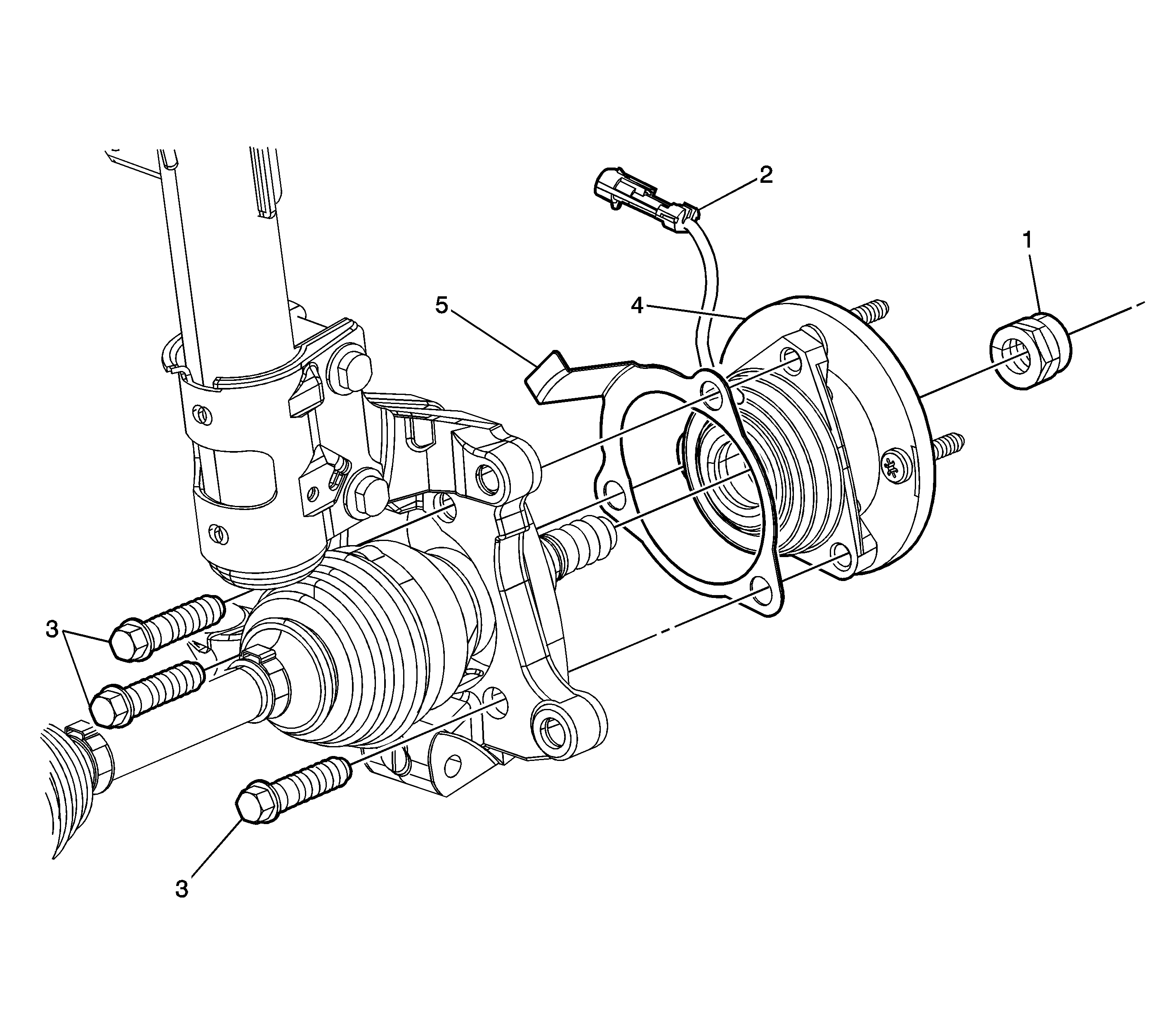
Callout | Component Name |
|---|---|
Preliminary Procedures
| |
1 |
Notice: Refer to Fastener Notice in the Preface section. Axle Shaft Nut Tighten |
2 | Wheel Speed Sensor Connector Tip |
3 |
Notice: This is a self-retaining fastener joint that does not require thread locking compounds. Do not attempt to clean the threads with a standard tap. If a standard tap is used, damage to the joint threads will occur. Wheel Bearing Bearing/Hub Assembly Mounting Bolt (Qty: 3) Tighten |
4 | Wheel Bearing/Hub Assembly Bearing Tip J 28733-B Wheel Hub Remover, 7208A Hub Remover - OTC, CJ129 Universal Hub Puller - Snap-On, 7394 Universal Hub Puller - OTC, or equivalent. |
5 | Wheel Bearing/Hub Assembly Spacer Tip |
