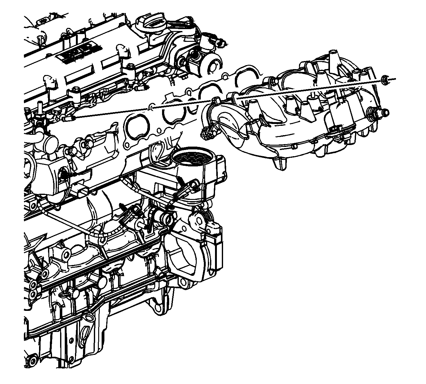
- Install a NEW intake manifold gasket.
- Install the intake manifold.
Notice: Refer to Fastener Notice in the Preface section.
- Install the intake manifold bolts and nuts.
Tighten
- Tighten the intake manifold bolts to 22 N·m (16 lb ft).
- Tighten the intake manifold nuts to 22 N·m (16 lb ft).
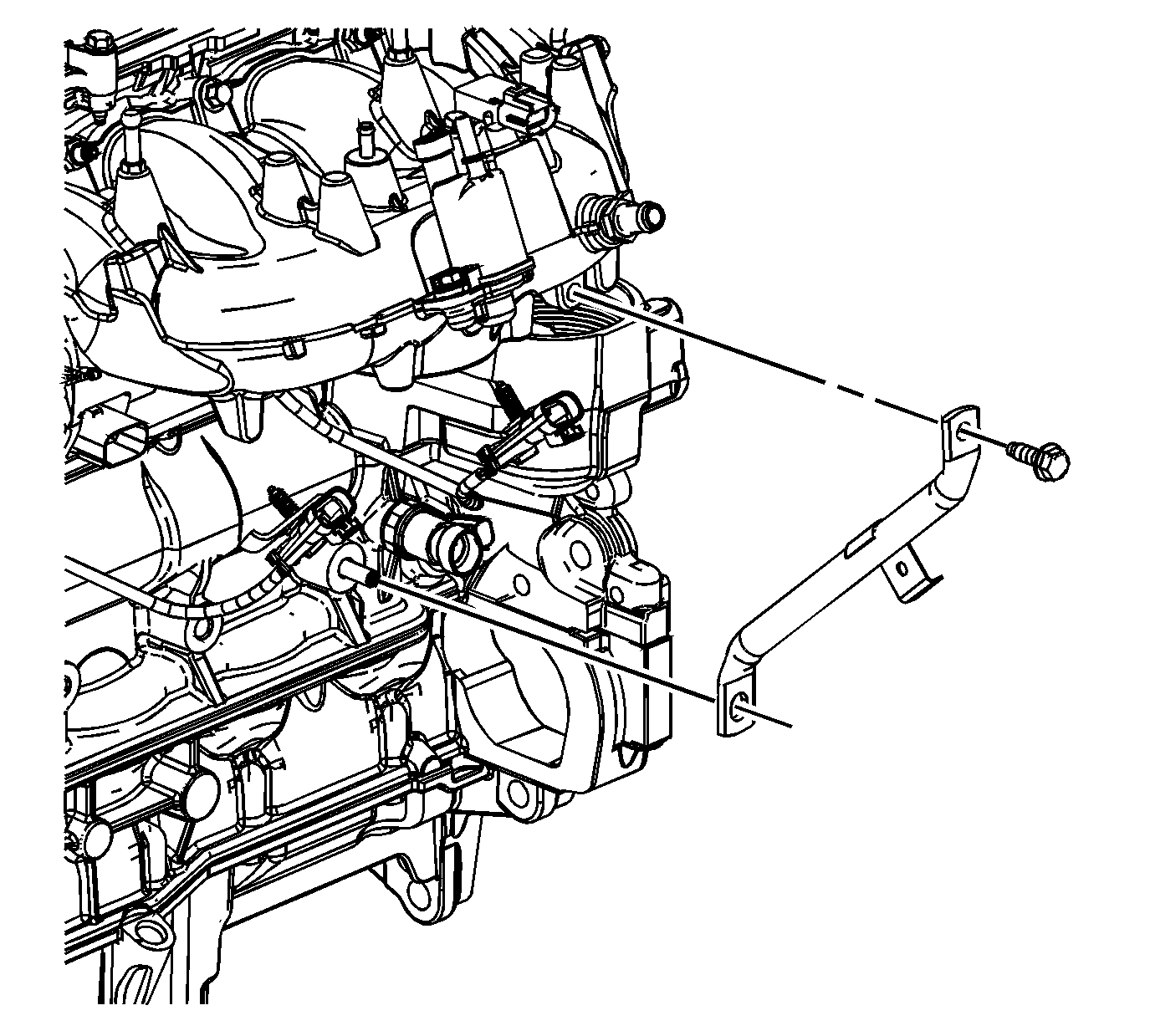
- Install the intake manifold brace.
- Install the intake manifold brace bolt.
Tighten
Tighten the intake manifold brace bolt to 22 N·m (16 lb ft).
- Connect the rear knock sensor to the intake manifold brace.
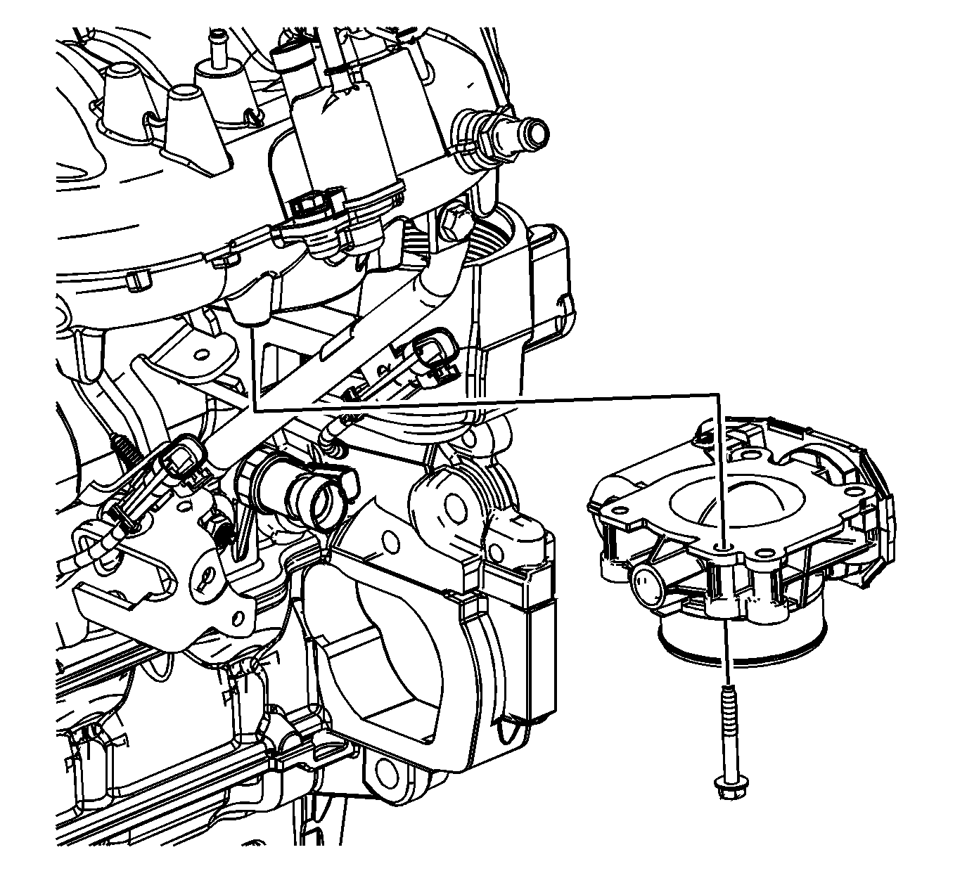
- Install the throttle body.
- Install the throttle body bolts.
Tighten
Tighten the throttle body bolts to 10 N·m (89 lb in).
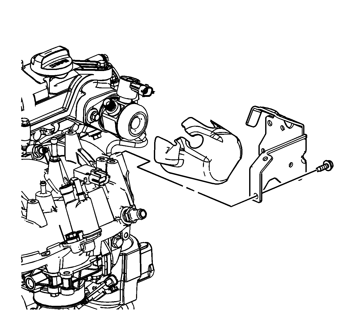
- Install the high pressure fuel pump noise insulator.
- Install the high pressure fuel pump cover.
- Install the high pressure fuel pump cover bolts.
Tighten
Tighten the fuel pump cover bolts to 10 N·m (89 lb in).
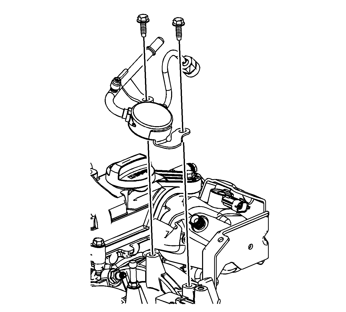
- Lubricate the high pressure fuel pump fuel feed line connection threads with clean 5W30 engine oil.
- Install the fuel feed line.
- Install the fuel feed line bolts.
- Connect the low pressure fuel line nut.
Tighten
- Tighten the low pressure fuel line nut to 30 N·m (22 lb ft).
- Tighten the fuel feed line bolts to 10 N·m (89 lb in).
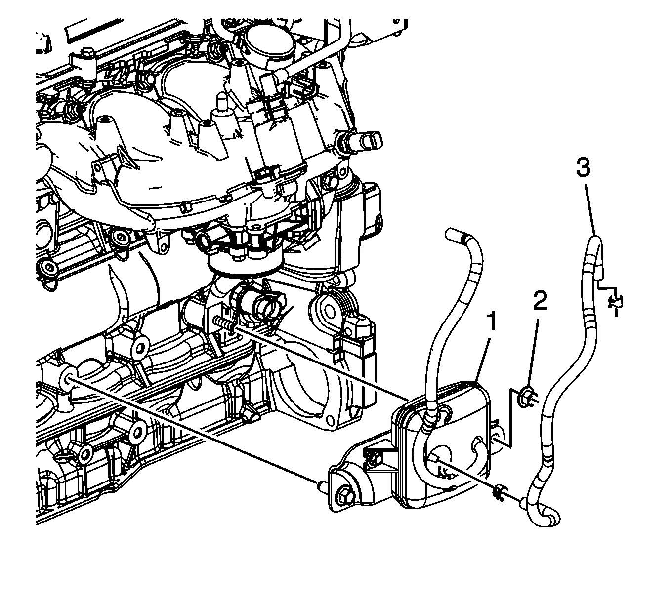
- If the engine is equipped with a charger
AIR bypass tank assembly, complete the following procedure:
| 16.1. | Install the charger AIR bypass valve tank assembly. |
| 16.2. | Tighten the charger AIR bypass valve tank assembly bolt. |
Tighten
Tighten the charger AIR bypass valve tank assembly bolt to 25 N·m (18 lb ft).
| 16.3. | Install the charger AIR bypass valve tank assembly nut. |
Tighten
Tighten the charger AIR bypass valve tank assembly nut to 25 N·m (18 lb ft).
| | Important: Ensure proper connection of the charger AIR bypass tube assemblies and retaining clips to maintain proper pressure. Connect each tube to the appropriate location. The tube with retaining clamp located on the charger AIR
bypass valve tank assembly left side connects to the charger AIR bypass valve solenoid. The right side permanently attached tube connects to the intake manifold.
|
| 16.4. | Connect the appropriate charger AIR bypass tube assembly to the intake manifold. |
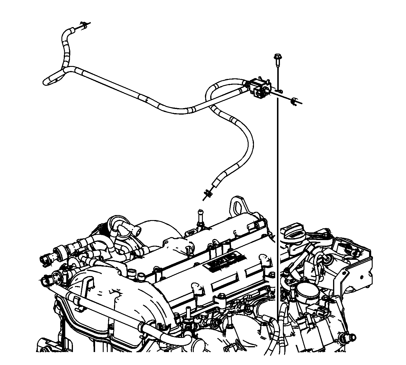
- If the engine is equipped with a charger AIR bypass
tank assembly, complete the following procedure:
| 17.1. | Install the charger AIR bypass valve solenoid with charger AIR bypass tube assemblies. |
| 17.2. | Install the charger AIR bypass valve solenoid bolts. |
Tighten
Tighten the charger AIR bypass valve solenoid bolts to 10 N·m (89 lb in).
| | Important: Ensure proper connection of the charger AIR bypass tube assemblies and retaining clips to maintain proper pressure. Connect each tube to the appropriate location.
|
| 17.3. | Connect the charger AIR bypass tube assemblies and clamps from the charger AIR bypass valve solenoid to the turbocharger and vehicle. |
| 17.4. | Connect the final charger AIR bypass tube assembly from the charger AIR bypass valve tank assembly to the charger AIR bypass valve solenoid. |
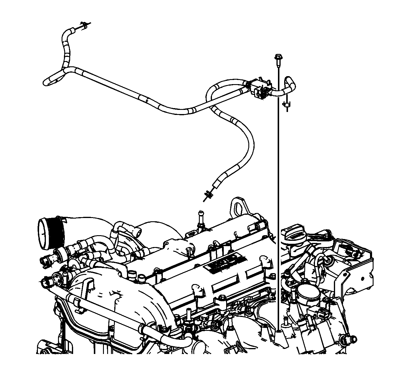
- If the engine is not equipped with a charger AIR bypass tank assembly, complete the following procedure:
| 18.1. | Install the charger AIR bypass valve solenoid with charger AIR bypass tube assemblies. |
| 18.2. | Install the charger AIR bypass valve solenoid bolts. |
Tighten
Tighten the charger AIR bypass valve solenoid bolts to 10 N·m (89 lb in).
| | Important: Ensure proper connection of the charger AIR bypass tube assemblies and retaining clips to maintain proper pressure. Connect each tube to the appropriate location.
|
| 18.3. | Connect the charger AIR bypass tube assemblies and clamps. |


