For 1990-2009 cars only
Removal Procedure
- Turn OFF the ignition.
- Remove the right front seat. Refer to Front Seat Replacement - Bucket.
- Remove the right side body hinge pillar trim panel. Refer to Body Hinge Pillar Trim Panel Replacement - Right Side.
- Carefully lift the floor carpet to access the yaw rate sensor.
- Disconnect the yaw rate sensor electrical connector.
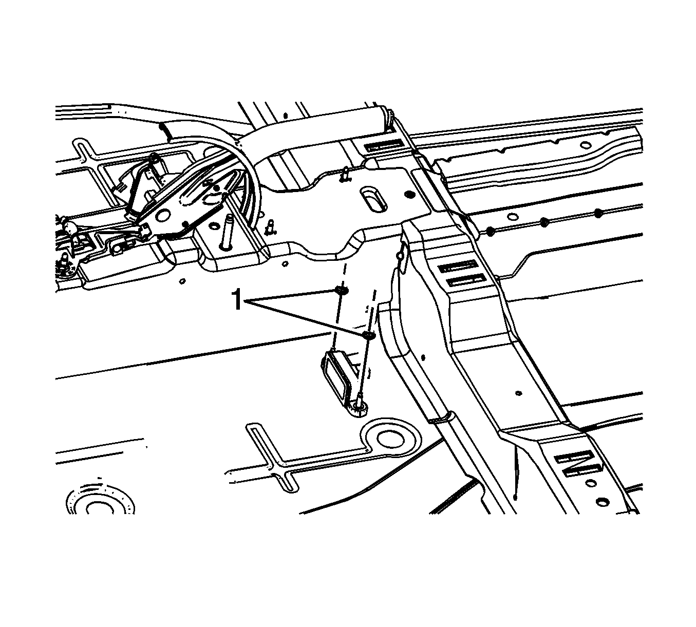
- Remove the yaw rate sensor nuts (1).
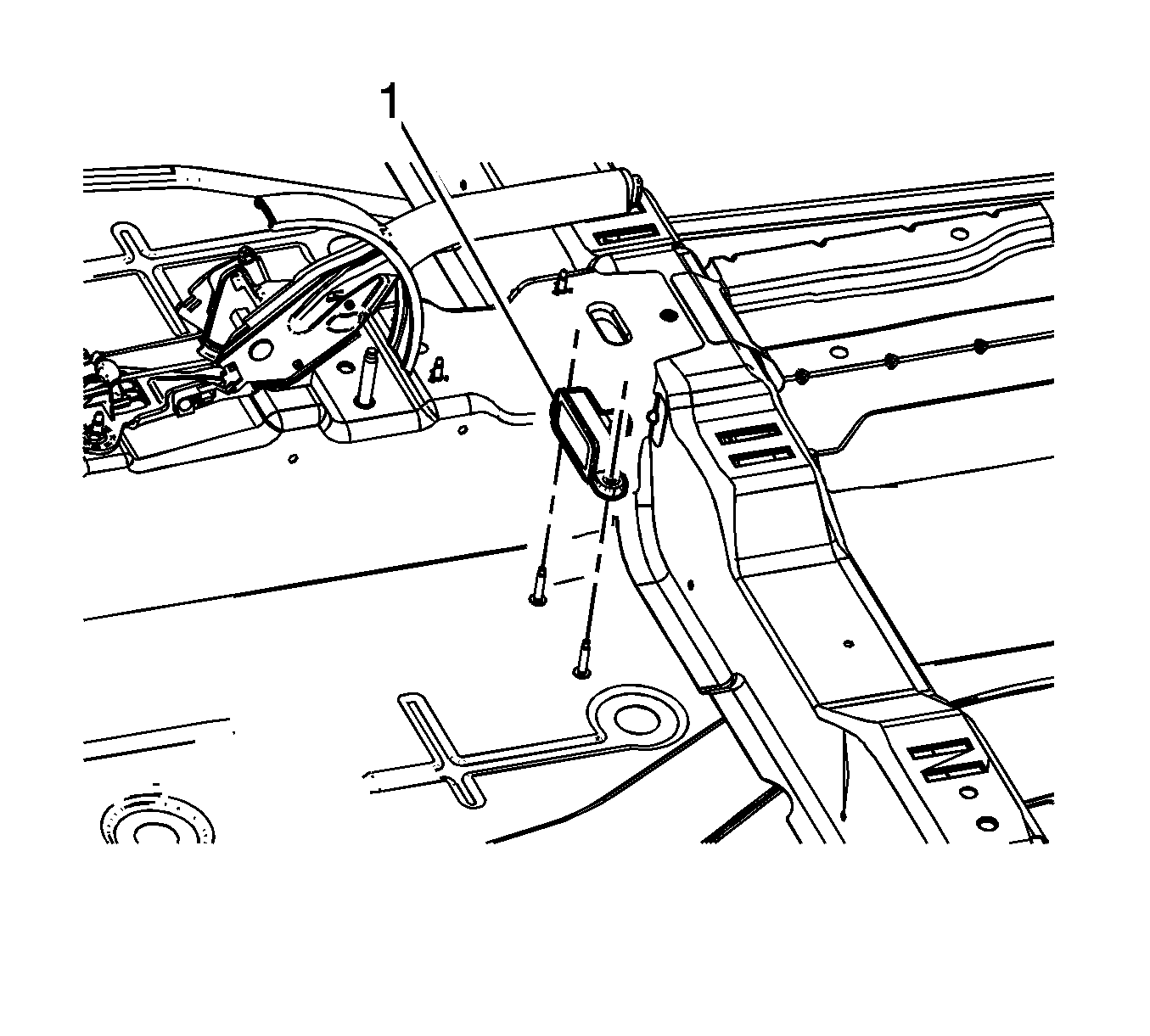
- Remove the yaw rate sensor (1).

To ease access to the yaw rate sensor, it may be necessary to carefully cut a small section of the floor carpeting neat the yaw rate sensor.

Installation Procedure
- Install the yaw rate sensor (1).
- Install the yaw rate sensor nuts (1).
- Connect the yaw rate sensor electrical connector.
- Carefully position the floor carpet to the vehicle floor.
- Install the right side body hinge pillar trim panel. Refer to Body Hinge Pillar Trim Panel Replacement - Right Side.
- Install the right front seat. Refer to Front Seat Replacement - Bucket.
- Install a scan tool.
- Using the special functions menu on the scan tool, perform the steering angle sensor calibration. Refer to Control Module References.
- Perform the Diagnostic System Check - Vehicle.

Notice: Refer to Fastener Notice in the Preface section.

Tighten
Tighten the nuts to 10 N·m (89 lb in).
