For 1990-2009 cars only
Special Tools
| • | J 44570 Bushing Remover/Installer Kit |
| • | J 45059 Torque Angle Meter |
Removal Procedure
- Raise and support the vehicle. Refer to Lifting and Jacking the Vehicle .
- Remove the rear tires and wheels. Refer to Tire and Wheel Removal and Installation .
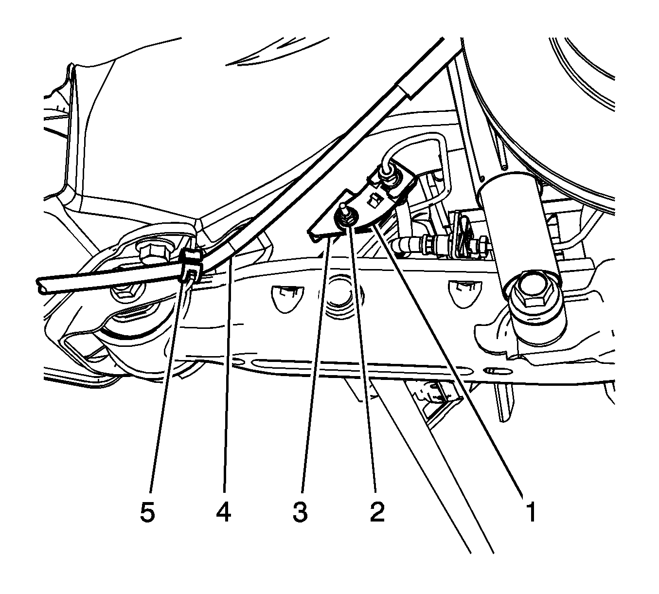
- Remove the rear brake hose bracket nut (2).
- Remove the rear brake hose bracket (1) from the frame (3).
- Remove the rear park brake cable from the (4) from the retaining clip (5).
- Remove the rear coil springs. Refer to Coil Spring Replacement .
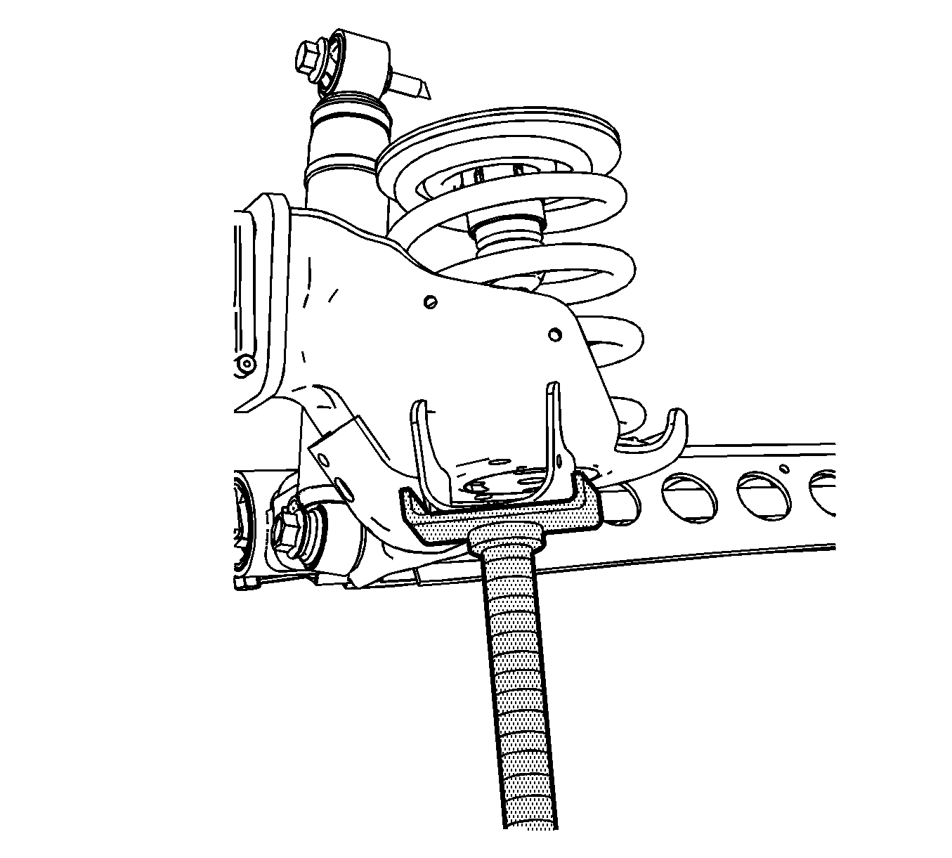
- Temporarily re-install the lower shock absorber bolts to support the rear axle.
- Using jack stands, raise the rear axle until rear suspension control arm bracket pivots away from the body.
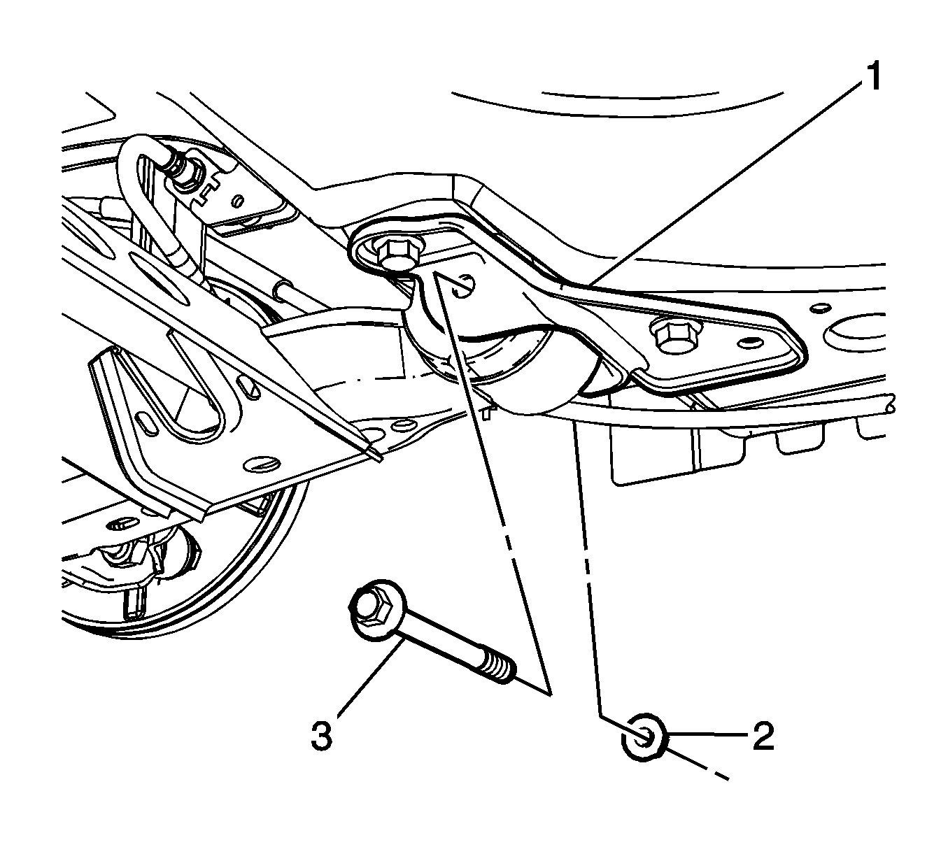
- Remove the nut (2) and bolt (3) for the rear suspension control arm bracket (1).
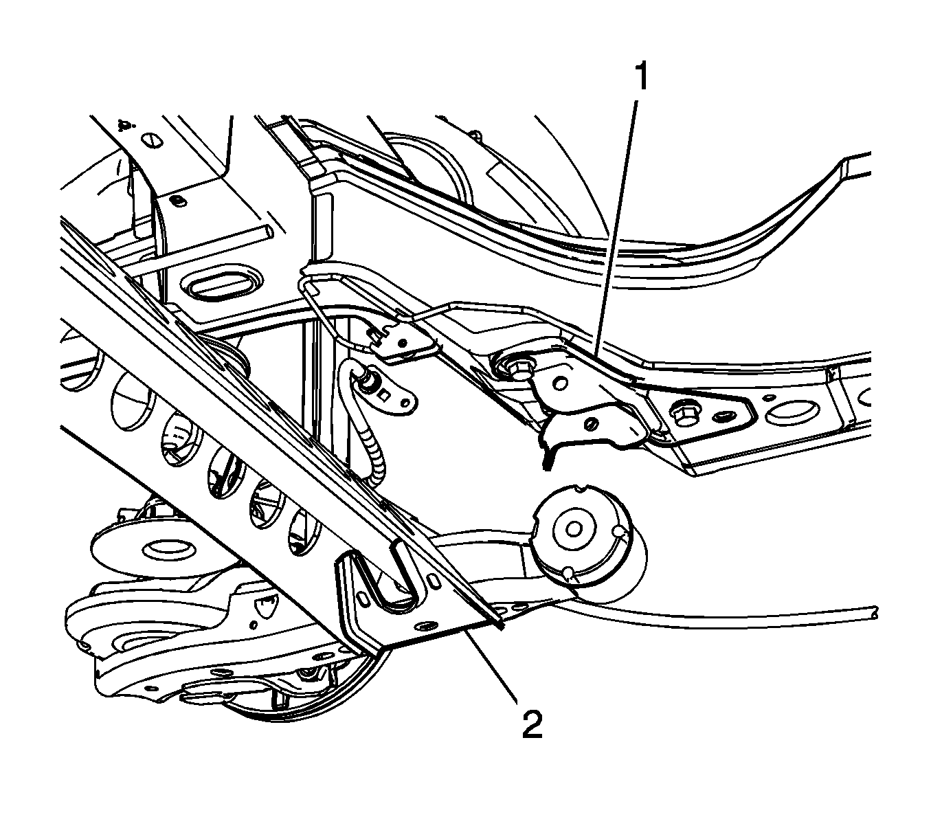
- Using the jack stand, lower the rear axle assembly (2) from the rear suspension control arm bracket (1).
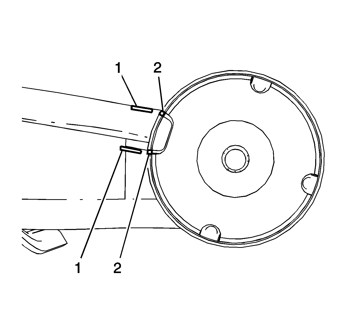
- Before removing the rear suspension insulator, scribe or paint reference marks (1) on the trailing arm in relationship to the large gap (2) on the old insulator.
- Position the J-44570-1 (2) between the axle sleeve and the bushing flange.
- Insert the J-44570-3 (1) through the J-44570-1 (2) and the rear suspension insulator.
- Using the J 44570 and a hammer, remove the rear suspension insulator from the rear suspension control arm.
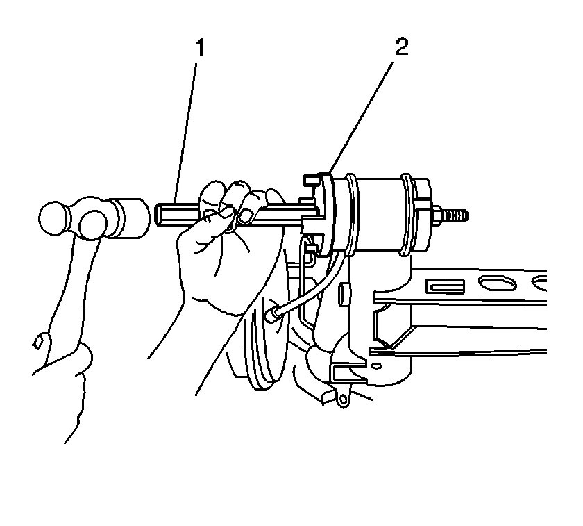
Important: It maybe necessary to use a hammer to lightly tap the J-44570-1 to fully seat it.
Important: Tightening the nut and washer by hand until snug.
Installation Procedure
- Position the rear suspension insulator (2) in the trailing arm and align the reference marks (1) for the proper alignment of the insulator (2).
- Position the J 44570-1 (2) onto the rear suspension insulator.
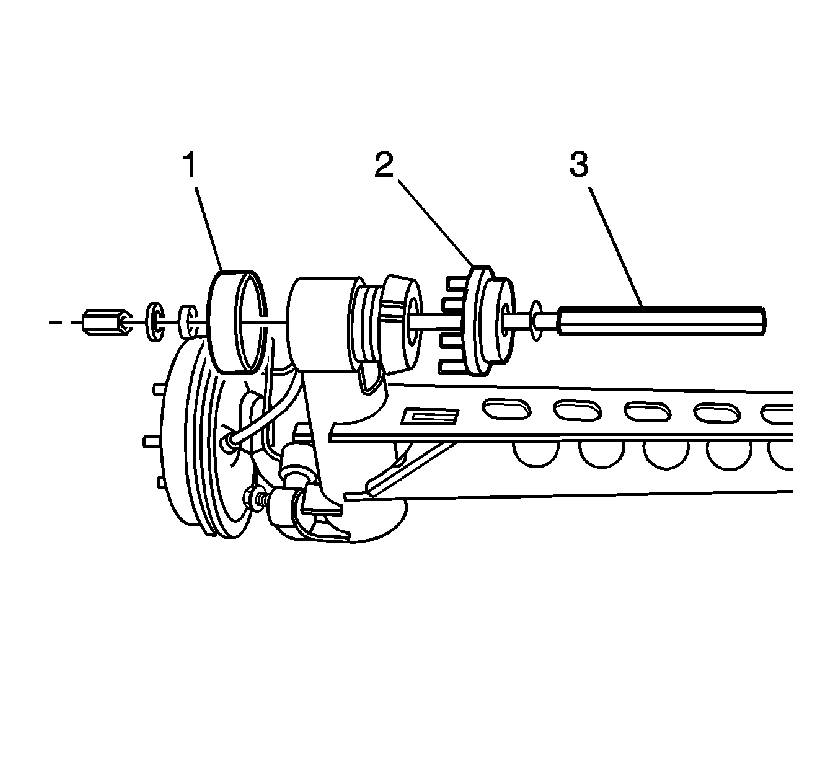
- Install the J 44570-3 (3) and the J 44570-1 (2) and the rear suspension insulator.
- Install the J 44570-2 (1) bearing, washer, and nut.
- Using the J 44570-2 (1), J 44570-1 (2) and the J 44570-3 (3), install the rear suspension insulator.
- Using the jack stand, position the rear axle assembly (2) in the rear suspension control arm bracket (1).
- Position the rear suspension control arm bracket (1) on the insulator (4).
- Install the bolt (3) and the nut (2).
- Install the rear coil springs. Refer to Coil Spring Replacement .
- Install the rear park brake cable (4) in the retaining clip (5).
- Position the rear brake hose bracket (1) on the frame (3).
- Install the rear brake hose bracket nut (2).
- Remove the jack stands.
- Install the tire and wheel assemblies. Refer to Tire and Wheel Removal and Installation .
- Lower the vehicle.



Notice: Refer to Fastener Notice in the Preface section.
Important: The bolt for the rear suspension insulator must be install so that the head of the bolt is on the inside of the bracket.
Tighten
Tighten the nut (2) to 90 N·m (66 lb ft). Using the
J 45059
, rotate the nut (2) an additional 30 degrees.

Tighten
Tighten the rear brake hose bracket nut (2) to 10 N·m (89 lb in).

