For 1990-2009 cars only
Special Tools
J 45059 Torque Angle Meter
Removal Procedure
- Raise and support the vehicle. Refer to Lifting and Jacking the Vehicle .
- Remove the tire and wheel assembly. Refer to Tire and Wheel Removal and Installation .
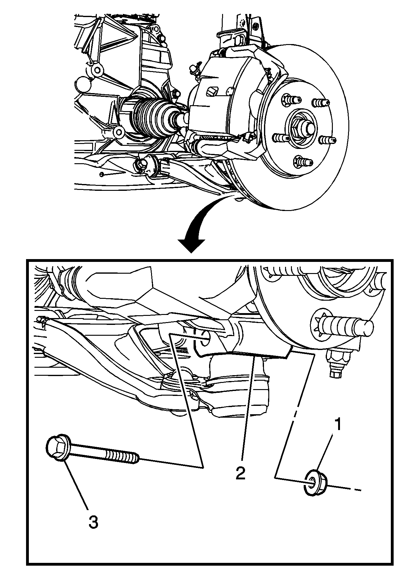
- Remove the front lower control arm ball stud nut (1).
- Remove the front lower control arm ball stud bolt (3) from the steering knuckle (1).
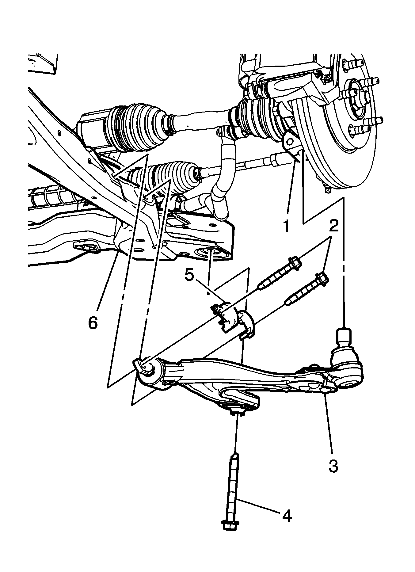
- Remove the drivetrain and front suspension frame bolt (4) from the drivetrain and front suspension frame (6).
- Remove the front lower control arm bolts (2), and the front lower control arm brackets (5).
- Remove the front lower control arm (3) from the steering knuckle (1) and the drivetrain and front suspension frame (6).


Installation Procedure
- Position the front lower control arm (3) on the drivetrain and front suspension frame (6).
- Install the drivetrain and front suspension frame bolt (4) in the frame (6).
- Install the front lower control arm brackets (5) and the lower control arm bolts (2).
- Install the front lower control arm (3) in the steering knuckle (1).
- Install the lower control arm ball stud bolt (3) in the steering knuckle (2).
- Install the lower control arm ball stud bolt nut (1).

Notice: Refer to Fastener Notice in the Preface section.
Tighten
Tighten the frame bolt (4) to 100 N·m (74 lb ft). Using the
J 45059
rotate the frame bolt (4) 180 degrees.
Tighten
Tighten the lower control arm bolts (2) to 55 N·m (41 lb ft).

Tighten
Tighten the lower control arm ball stud nut (1) to 50 N·m (37 lb ft). Using the
J 45059
rotate the lower control arm ball
stud nut (1) 30 degrees.
