For 1990-2009 cars only
Special Tools
J 45059 Torque Angle Meter
Removal Procedure
- Raise and support the vehicle. Refer to Lifting and Jacking the Vehicle .
- Remove the tire and wheel assembly. Refer to Tire and Wheel Removal and Installation .
- Remove the rear brake drum, if equipped. Refer to Brake Drum Replacement .
- Remove the rear brake rotor, if equipped. Refer to Rear Brake Rotor Replacement .
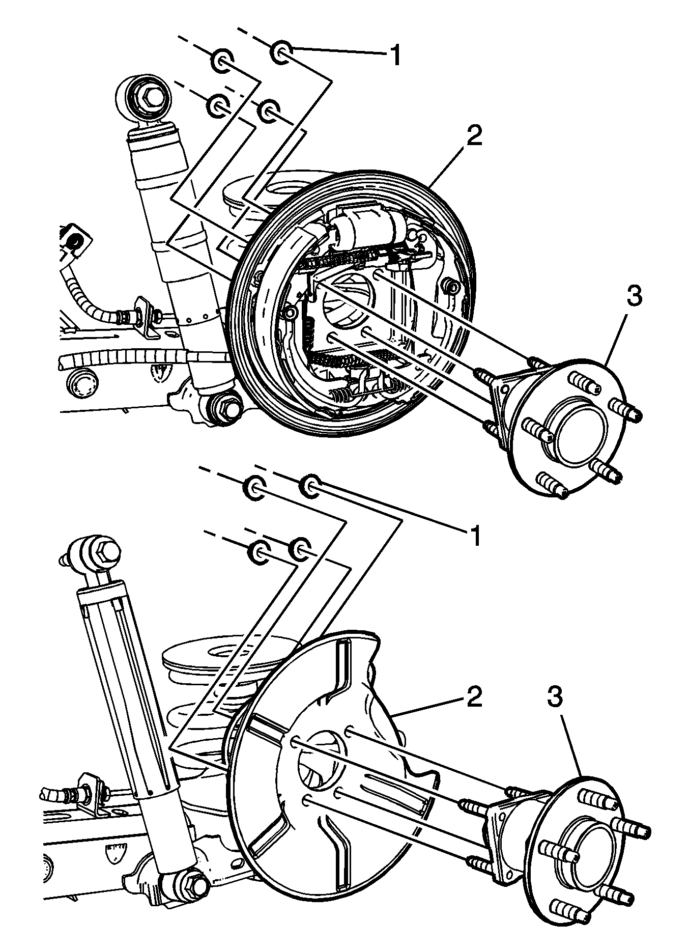
- Remove the wheel bearing/hub mounting nuts (1) from the wheel bearing/hub assembly (3).
- Remove the wheel bearing/hub assembly (3) from the trailing arm and brake backing plate (2).
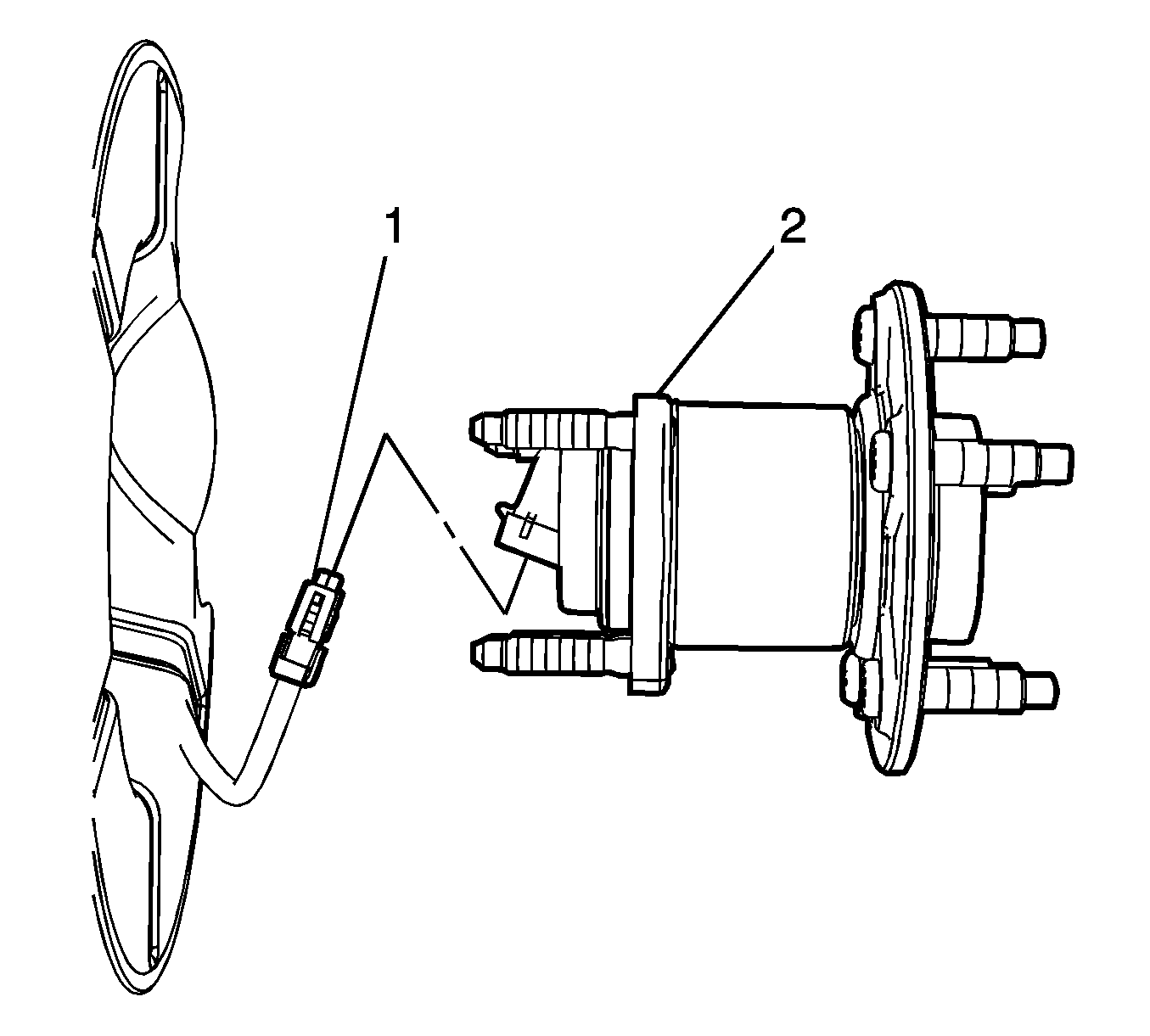
- Disconnect the wheel speed sensor electrical connector (1) from the wheel bearing/hub assembly (2).
Important: If removing the rear wheel bearing to service other suspension components, it is NOT necessary to completely disassemble the rear brake assemblies. Remove the rear brake assemblies as a unit and relocate to the side.


Installation Procedure
- Reconnect the wheel speed sensor electrical connector (1) to the wheel bearing/hub assembly (2).
- Position the wheel bearing/hub assembly (3) in the trailing arm and brake backing plate (2).
- Install the wheel bearing/hub mounting nuts (1).
- Install the rear brake drum, if equipped. Refer to Brake Drum Replacement .
- Install the rear brake rotor, if equipped. Refer to Rear Brake Rotor Replacement .
- Install the tire and wheel assembly. Refer to Tire and Wheel Removal and Installation .
- Remove the support and lower the vehicle.


Notice: Refer to Fastener Notice in the Preface section.
Tighten
Tighten the wheel bearing/hub mounting nuts to 45 N·m (33 lb ft). Using the
J 45059
, rotate the mounting nuts an additional 30 degrees.
