GM Service Manual Online
For 1990-2009 cars only
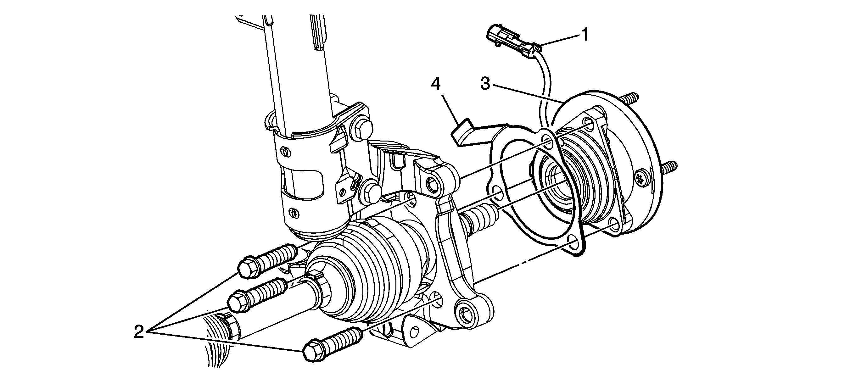
Object Number: 2005523  Size: SF

Callout

Component Name

Preliminary Procedures

  1. Raise and support the vehicle. Refer to Lifting and Jacking the Vehicle.
  2. Remove the front tire and wheel. Refer to Tire and Wheel Removal and Installation.
  3. Remove the brake rotor. Refer to Front Brake Rotor Replacement.

1

Wheel Speed Sensor Electrical Connector

Tip
Push inward on the wheel drive shaft when removing the wheel bearing/hub assembly from the knuckle. This will allow the removal and installation of the wheel speed sensor electrical connector (if equipped).

3

Wheel Bearing Bearing/Hub Assembly Mounting Bolt (Qty: 3)

Notice: Refer to Fastener Notice in the Preface section.

Tighten
115 N·m (85 lb ft)

4

Wheel Bearing/Hub Assembly Bearing

Procedure

Separate the wheel drive shaft from the steering knuckle. Refer to Wheel Drive Shaft Replacement.

5

Wheel Bearing/Hub Assembly Spacer