For 1990-2009 cars only
Special Tools
J 45059 Torque Angle Meter
Removal Procedure
- Raise and support the vehicle. Refer to Lifting and Jacking the Vehicle.
- Remove the tire and wheel assembly. Refer to Tire and Wheel Removal and Installation.
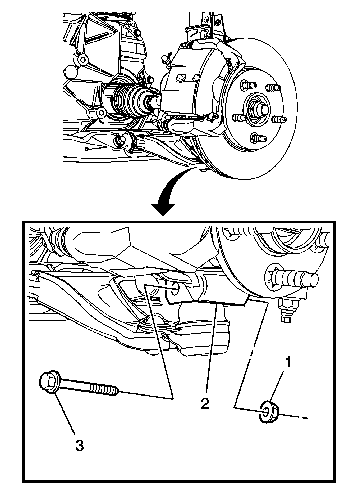
- Remove the front lower control arm ball stud nut (1).
- Remove the front lower control arm ball stud bolt (3) from the steering knuckle (2).
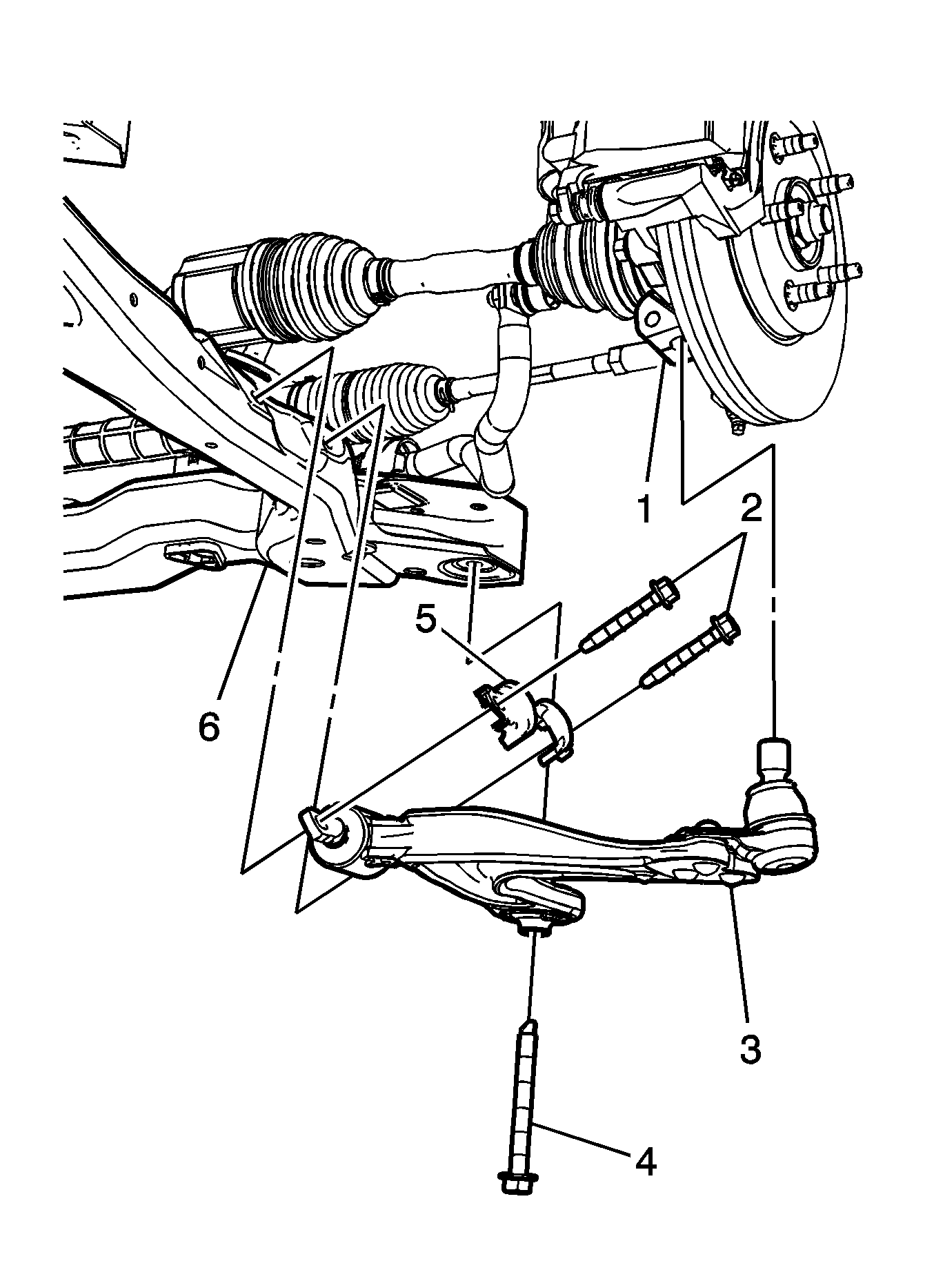
- Remove the drivetrain and front suspension frame bolt (4) from the drivetrain and front suspension frame (6).
- Remove the front lower control arm bolts (2), and the front lower control arm brackets (5).
- Remove the front lower control arm (3) from the steering knuckle (1) and the drivetrain and front suspension frame (6).


Installation Procedure
- Position the front lower control arm (3) on the drivetrain and front suspension frame (6).
- Install the drivetrain and front suspension frame bolt (4) in the frame (6).
- Install the front lower control arm brackets (5) and the lower control arm bolts (2) and tighten to 55 N·m (41 lb ft).
- Install the front lower control arm (3) in the steering knuckle (1).
- Install the lower control arm ball stud bolt (3) in the steering knuckle (2).
- Install the lower control arm ball stud bolt nut (1).

Caution: Refer to Fastener Caution in the Preface section.
Tighten the frame bolt (4) to 100 N·m (74 lb ft). Using the J 45059 rotate the frame bolt (4) 180 degrees.

Tighten the lower control arm ball stud nut (1) to 50 N·m (37 lb ft). Using the J 45059 rotate the lower control arm ball stud nut (1) 30 degrees.
