For 1990-2009 cars only
Removal Procedure
- Remove the throttle body. Refer to Throttle Body Assembly Replacement .
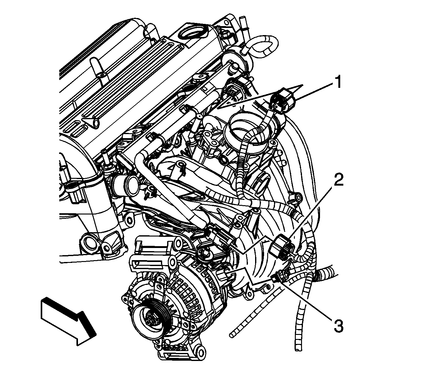
- Disconnect the fuel injector electrical connector (2).
- Raise and suitably support the vehicle. Refer to Lifting and Jacking the Vehicle .
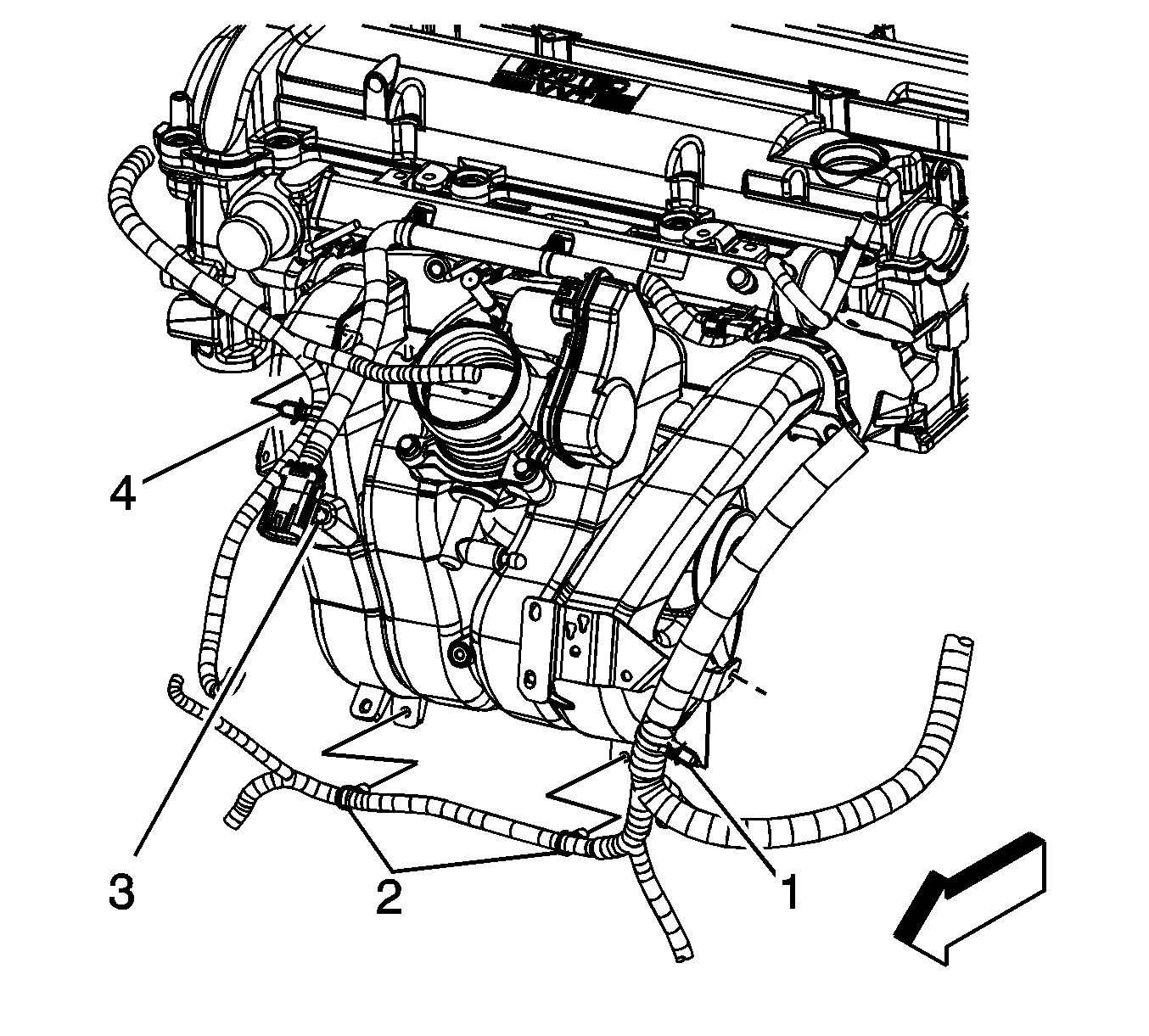
- Disconnect the engine harness clips (2 and 4) from the intake manifold.
- Lower the vehicle.
- Remove the oil level indicator tube. Refer to Oil Level Indicator Tube Replacement .
- Disconnect the fuel injector electrical connector clip (3) from the intake manifold.
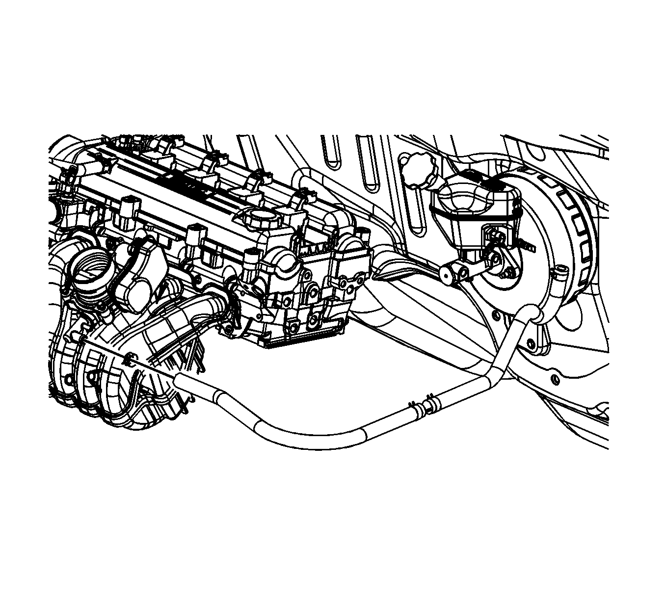
- Reposition the vacuum brake booster hose clamp at the intake manifold.
- Remove the vacuum brake booster hose from the intake manifold.
- Disconnect the evaporative emission (EVAP) canister purge tube from the intake manifold and the EVAP solenoid. Refer to Plastic Collar Quick Connect Fitting Service .
- Remove the fuel rail. Refer to Fuel Injection Fuel Rail Assembly Replacement .
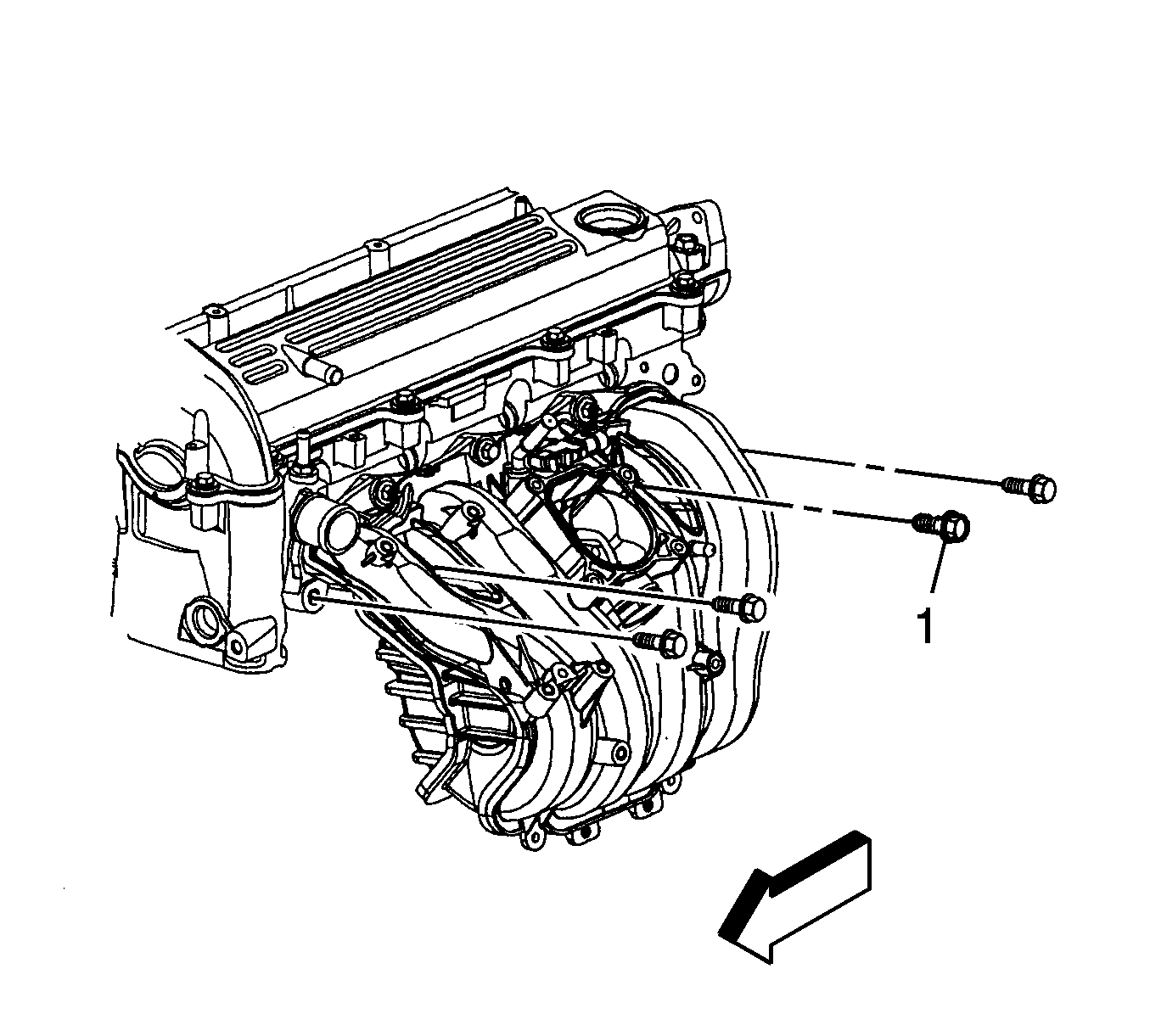
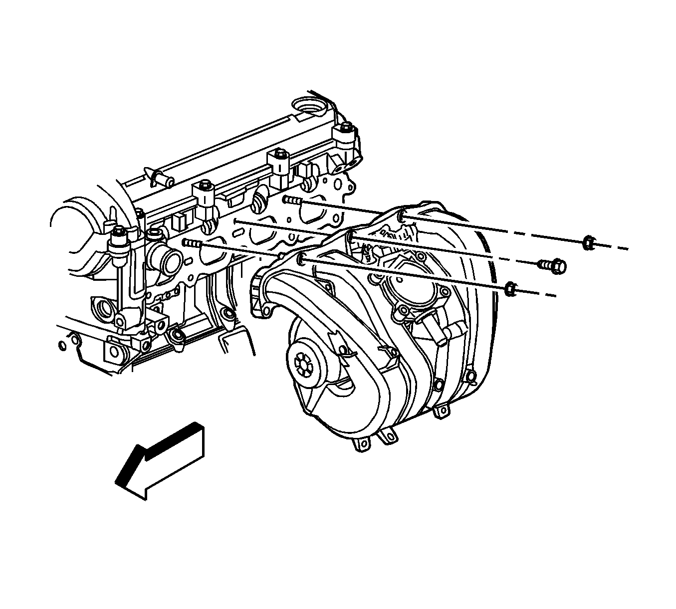
- Remove the intake manifold lower bolts.
- Remove the intake manifold upper bolt and nuts.
- Remove the intake manifold.
- Inspect the intake manifold O-ring seals.
Note: The intake manifold O-ring seals are reusable, only replace the seals if damage has occurred.
Installation Procedure
- Install NEW intake manifold O-ring seals if necessary.
- Install the intake manifold.
- Install the intake manifold upper bolt and nuts.
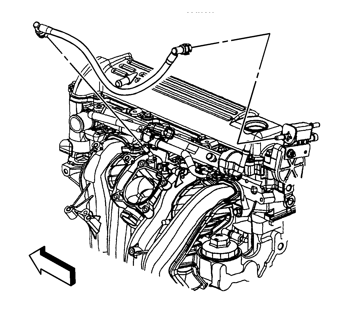
- Install the intake manifold lower bolts (1). Tighten the bolts/nuts to 10 N·m (89 lb in) .
- Install the fuel rail. Refer to Fuel Injection Fuel Rail Assembly Replacement .
- Connect the EVAP canister purge tube to the intake manifold and the EVAP solenoid. Refer to Plastic Collar Quick Connect Fitting Service .
- Install the vacuum brake booster hose to the intake manifold.
- Position the vacuum brake booster hose clamp at the intake manifold.
- Connect the fuel injector electrical connector clip (3) to the intake manifold.
- Install the oil level indicator tube. Refer to Oil Level Indicator Tube Replacement .
- Raise and support the vehicle.
- Connect the engine harness clips (2 and 4) to the intake manifold.
- Lower the vehicle.
- Connect the fuel injector electrical connector (2).
- Install the throttle body. Refer to Throttle Body Assembly Replacement .
Caution: Refer to Fastener Caution in the Preface section.
