Special Tools
| • | J 45341
Rear Wheel Drive Shaft Removal Tool |
Removal Procedure
- Raise and support the vehicle. Refer to
Lifting and Jacking the Vehicle.
- Remove the RH tire and wheel assembly. Refer to
Tire and Wheel Removal and Installation.
- Disconnect the stabilizer shaft link. Refer to
Stabilizer Shaft Link Replacement.
- Disconnect the outer tie rod assembly from the steering knuckle. Do NOT loosen the tie rod adjustment jamb nut. Refer to
Steering Linkage Outer Tie Rod Replacement.
- Rotate the steering knuckle to access the wheel drive shaft inner joint.
- Assemble the
J 45341
and the
SA9173G
to the wheel drive shaft inner tripot housing assembly.

- Using the
J 45341
and the
SA9173G
, separate the wheel drive shaft from the intermediate drive shaft.
- Reposition and support the wheel drive shaft from the intermediate drive shaft.
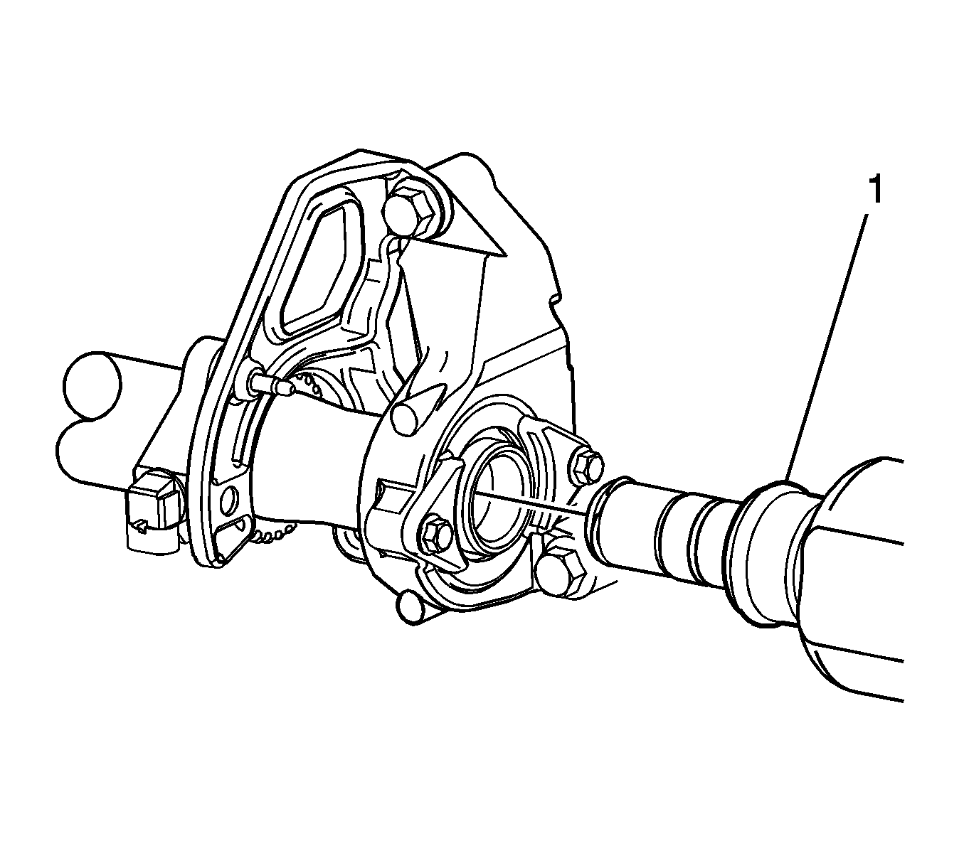
- Inspect the wheel drive shaft-to-intermediate drive shaft seal (1) for excessive wear, damage, and/or contamination and replace if necessary.

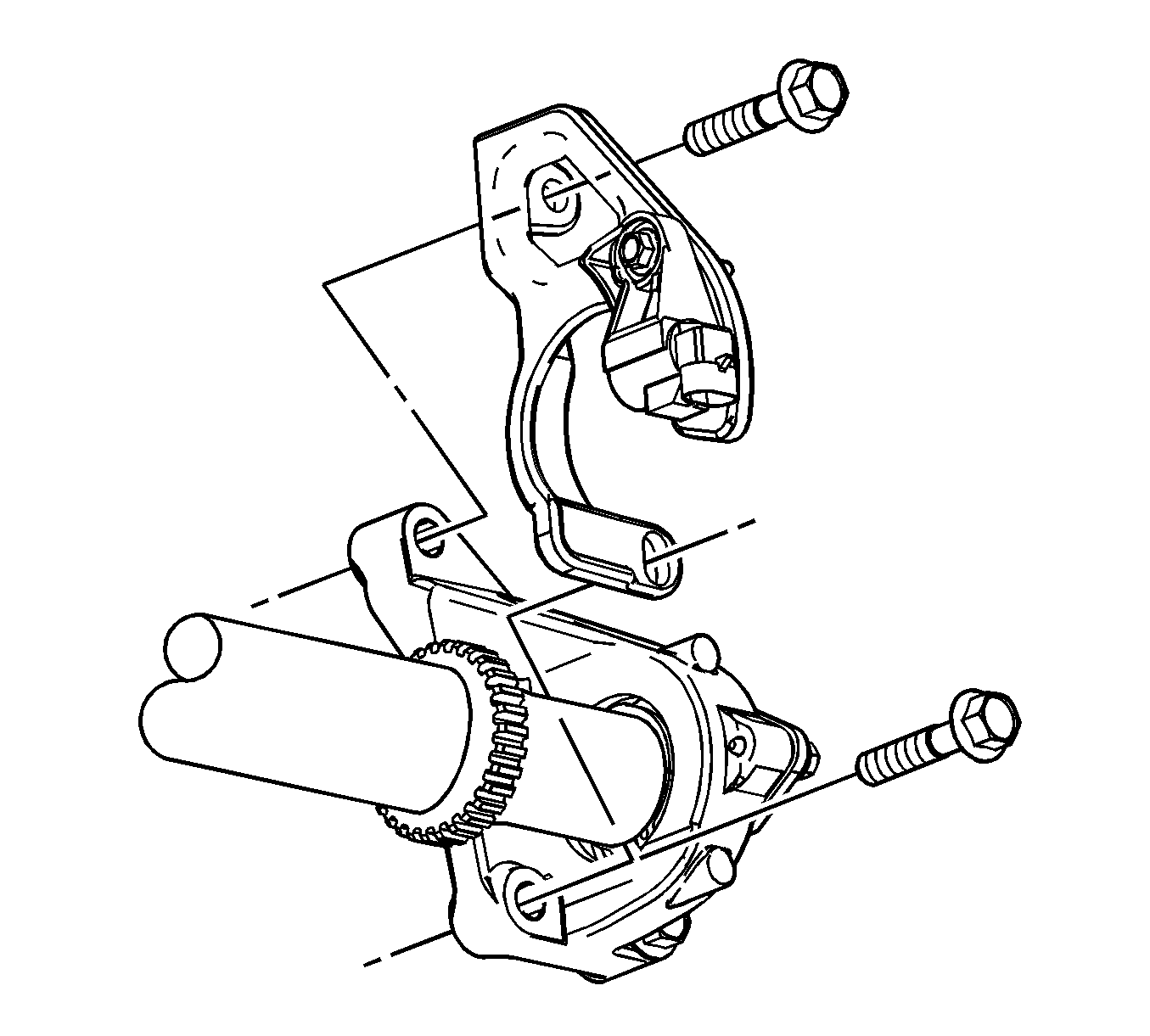
- Disconnect the electrical connector from the vehicle speed sensor.
- Remove the rear, or LH intermediate drive shaft bracket-to-engine block bolts, and remove the vehicle speed sensor with the bracket.

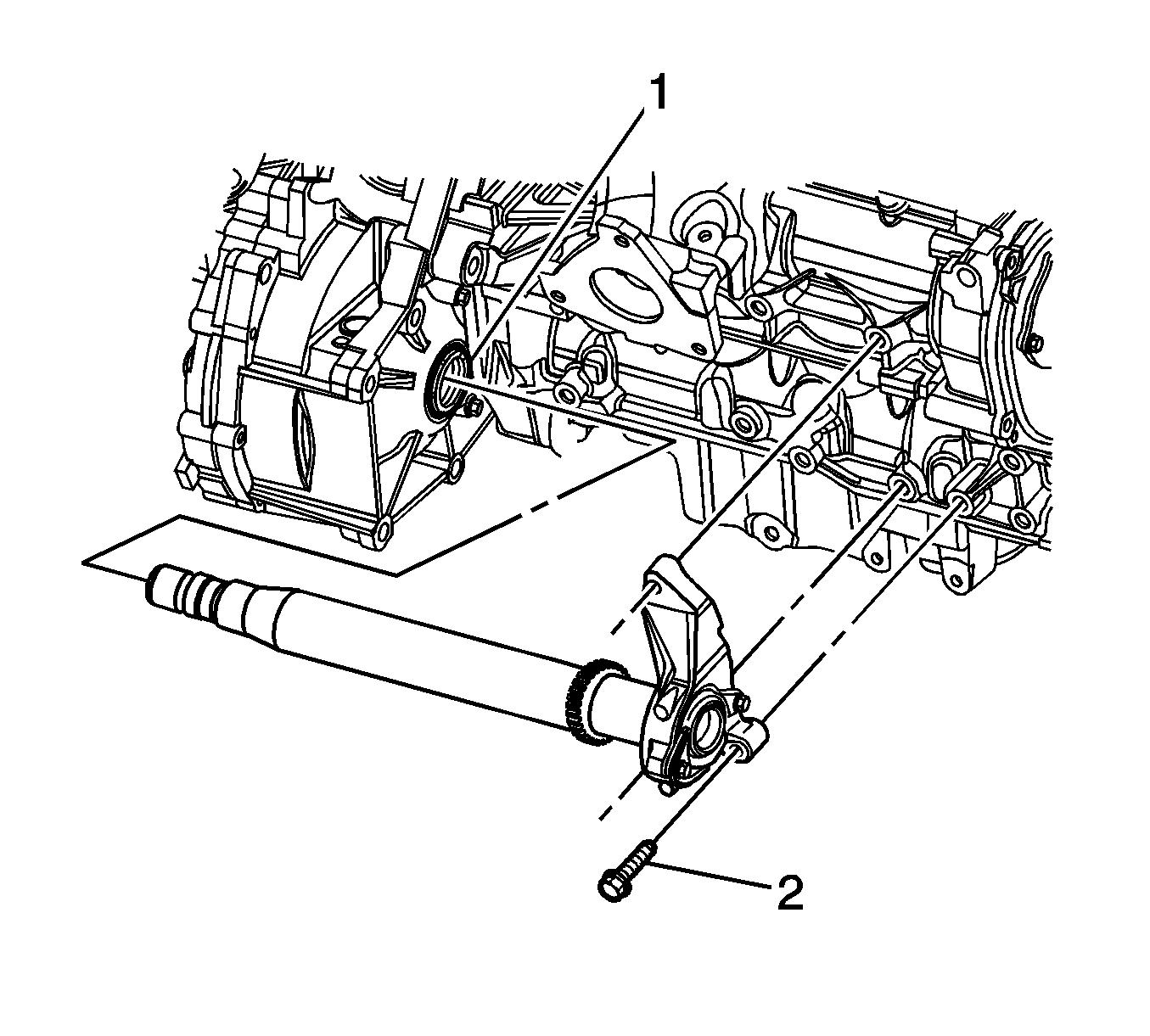
- Remove the remaining intermediate shaft bracket-to-engine block bolt (2).
- Using care to not damage the transaxle output shaft seal (1), remove the intermediate drive shaft assembly.
- Inspect the transaxle output shaft seal (1) for damage and/or contamination and replace if necessary. Refer to
Axle Seals Replacement for the MU3 Transaxle.
Installation Procedure

- Install the
SA91112T
into the transaxle output shaft
seal (1).
- Install the intermediate drive shaft into the transaxle until the drive shaft splines are past the seal (1), remove the
SA91112T
, then fully install the drive shaft.
- Install, but do NOT tighten the intermediate drive shaft bracket-to-engine block forward, or RH bolt (2).

- Position the vehicle speed sensor with the bracket to the intermediate drive shaft bracket, and install but
do NOT tighten the remaining intermediate drive shaft bracket-to-engine block bolts.
Caution: Refer to Fastener Caution in the Preface section.
- Tighten the intermediate drive shaft bracket-to-engine block bolts, beginning with the upper bolt.
Tighten the bolts to
50 N·m (37 lb ft).
- Connect the electrical connector to the vehicle speed sensor.

- Apply a very small amount of grease, GM P/N 1051344 (Canadian P/N 993037),
or equivalent to the splines of the wheel drive shaft inner joint.
- Install the wheel drive shaft into the intermediate drive shaft (1).
- Verify that the wheel drive shaft is properly engaged:
| • | Grasp the inner tripod housing and pull the inner housing outward. Do NOT pull on the wheel drive axle shaft. |
| • | The wheel drive shaft will remain firmly in place when properly engaged. |
- Connect the outer tie rod assembly to the steering knuckle. Refer to
Steering Linkage Outer Tie Rod Replacement.
- Connect the stabilizer shaft link. Refer to
Stabilizer Shaft Link Replacement.
- Install the tire and wheel assembly. Refer to
Tire and Wheel Removal and Installation.
- Lower the vehicle.
- Inspect the transaxle fluid level.


