For 1990-2009 cars only
Warning: Refer to Brake Fluid Irritant Warning in the Preface section.
Caution: Refer to Brake Fluid Effects on Paint and Electrical Components Caution in the Preface section.
Removal Procedure
- Disconnect the battery negative cable. Refer to Battery Negative Cable Disconnection and Connection.
- Without disconnecting the wiring harness connectors, reposition the electrical center and the powertrain control modules from the electrical center bracket and remove the underhood electrical center bracket. Refer to Underhood Electrical Center or Junction Block Bracket Replacement.
- Remove the brake fluid from the master cylinder reservoir and discard into an approved container.
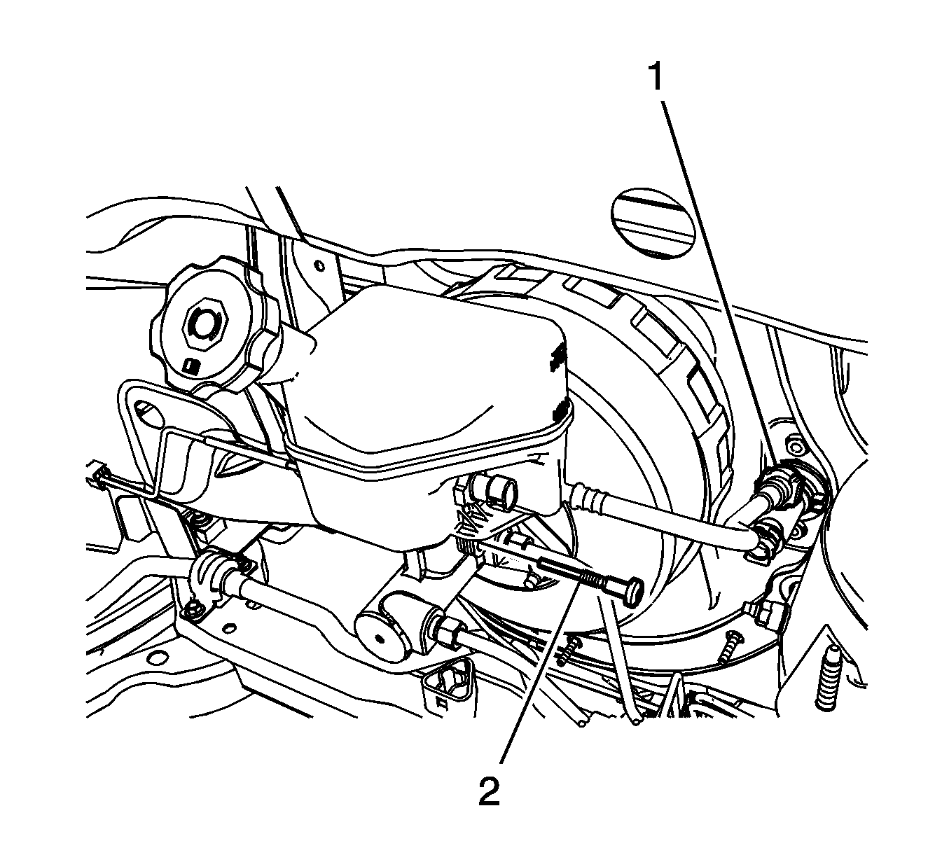
- Disconnect the quick connect (1) on the master cylinder reservoir clutch hose from the clutch master cylinder, if equipped.
- Disconnect the brake fluid level indicator switch electrical connector.
- Remove the master cylinder reservoir bolt (2).
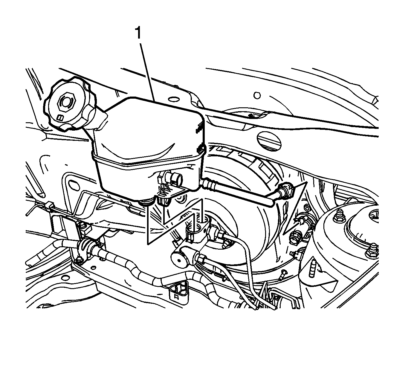
- Lift the master cylinder reservoir (1) upward from the master cylinder.
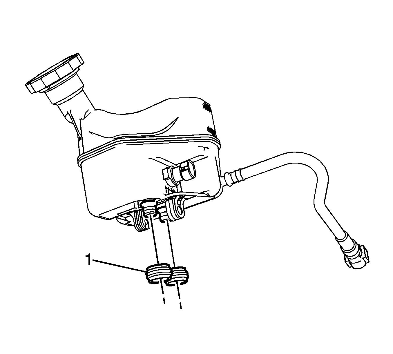
- Remove the master cylinder reservoir seals (1).
- Inspect the master cylinder reservoir cap and seal for damage and replace if necessary.

Plug the hose and cap the clutch master cylinder inlet fitting to prevent brake fluid loss and contamination.


Installation Procedure
- Lubricate the master cylinder reservoir seals (1) and the reservoir bayonets with clean, fresh DOT 3 motor vehicle brake fluid from a sealed container.
- Install the master cylinder reservoir seals.
- Install the master cylinder reservoir (1) to the master cylinder by firmly pressing downward.
- Connect the master cylinder reservoir clutch hose quick connect (1) to the clutch master cylinder, if equipped.
- Install the master cylinder reservoir bolt (2).
- Connect the brake fluid level indicator switch electrical connector.
- Install the underhood electrical center bracket and position the electrical center and the powertrain control modules to the electrical center bracket. Refer to Underhood Electrical Center or Junction Block Bracket Replacement.
- Connect the battery negative cable. Refer to Battery Negative Cable Disconnection and Connection.
- Fill the master cylinder reservoir to the proper level. Refer to Master Cylinder Reservoir Filling.


Caution: Refer to Fastener Caution in the Preface section.
Tighten
Tighten the bolt to 6 N·m (53 lb in).
