For 1990-2009 cars only
Warning: Refer to Brake Fluid Irritant Warning in the Preface section.
Caution: Refer to Brake Fluid Effects on Paint and Electrical Components Caution in the Preface section.
Removal Procedure
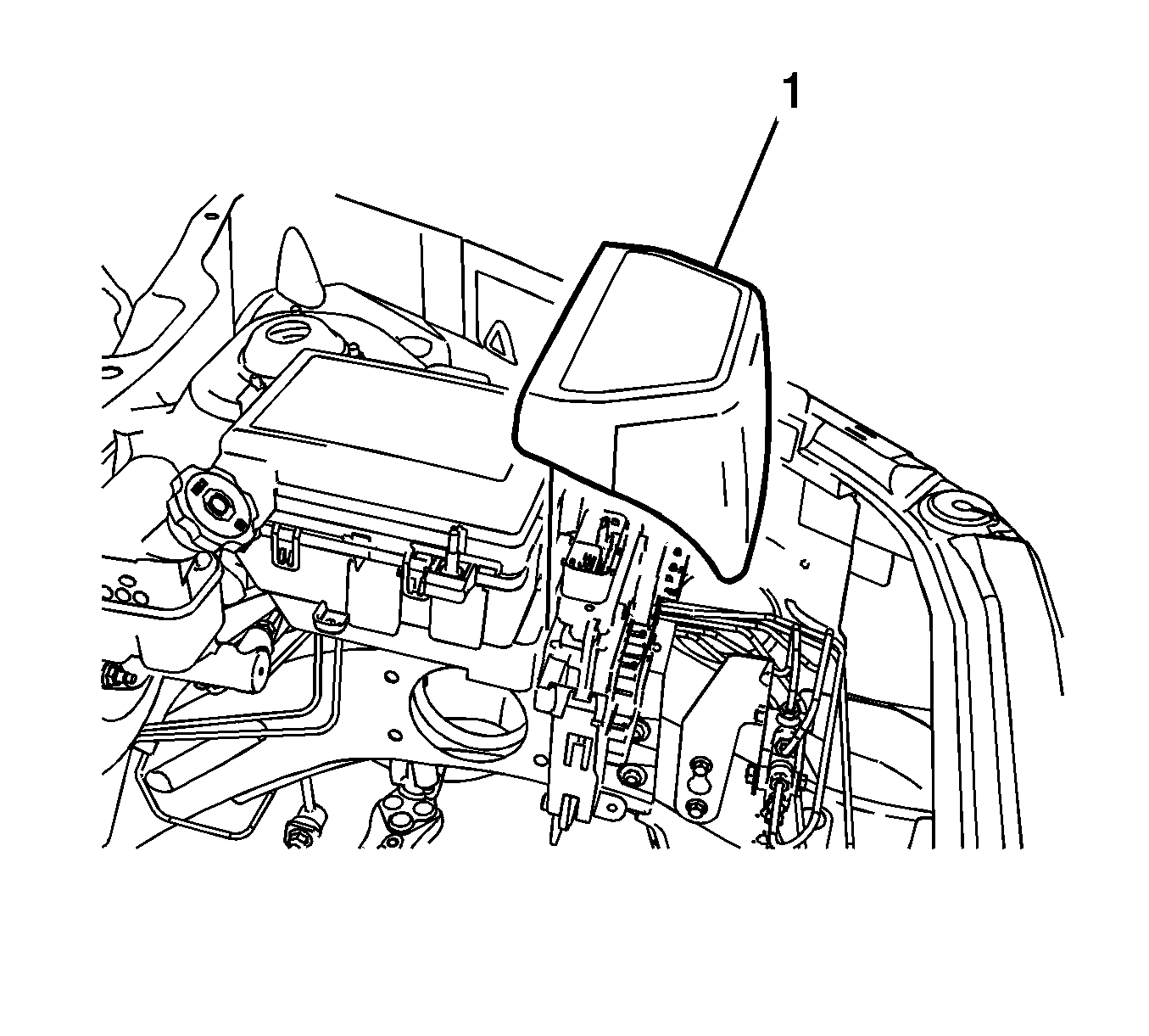
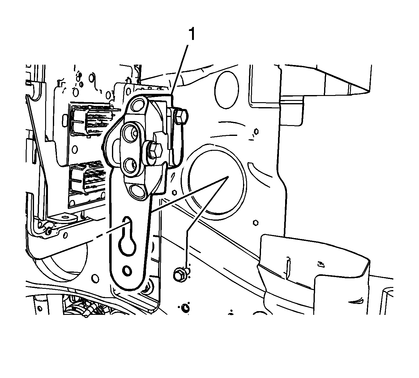
- Remove the engine control module (ECM) cover (1).
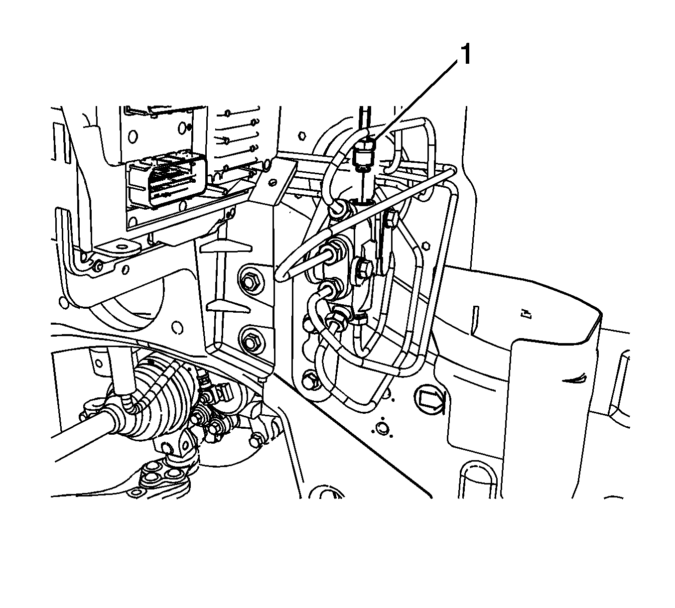
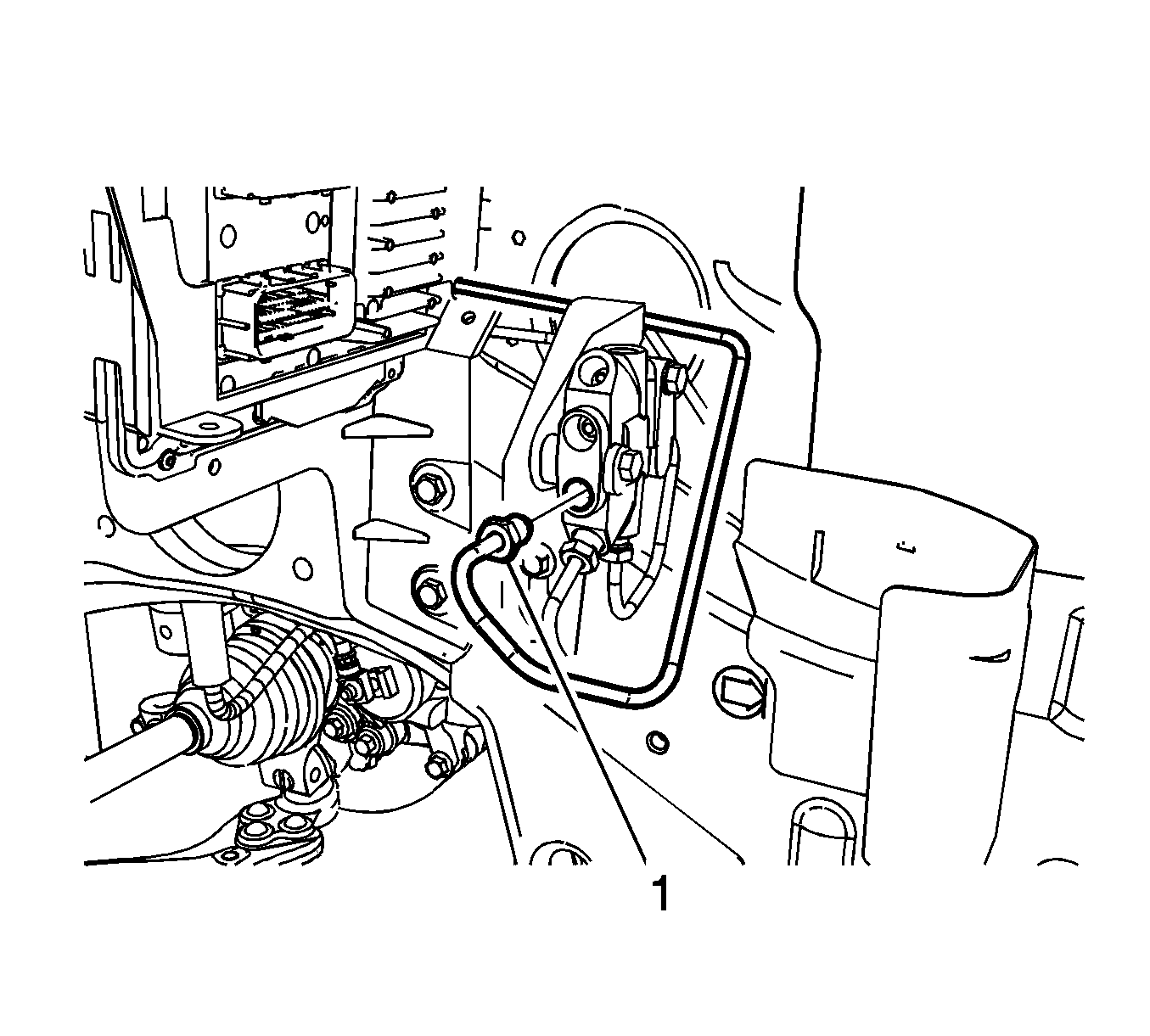
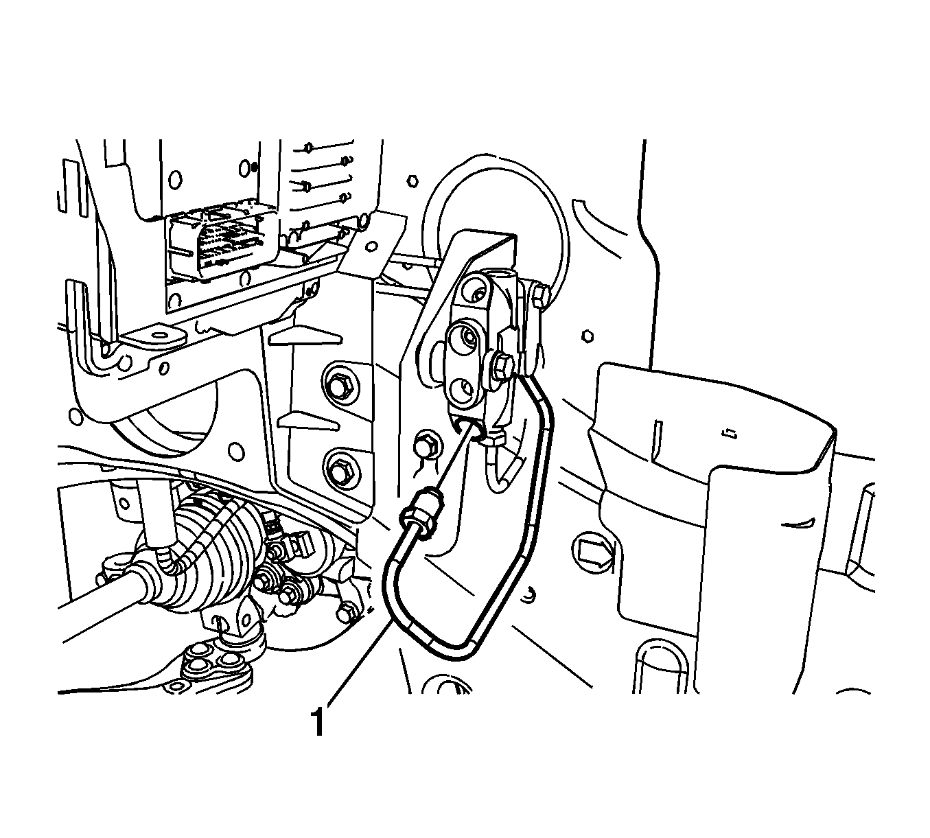
- Disconnect the brake master cylinder secondary inlet brake pipe fitting (1).
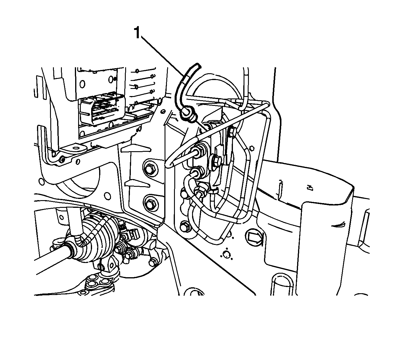
- Disconnect the RF brake pipe fitting (1).
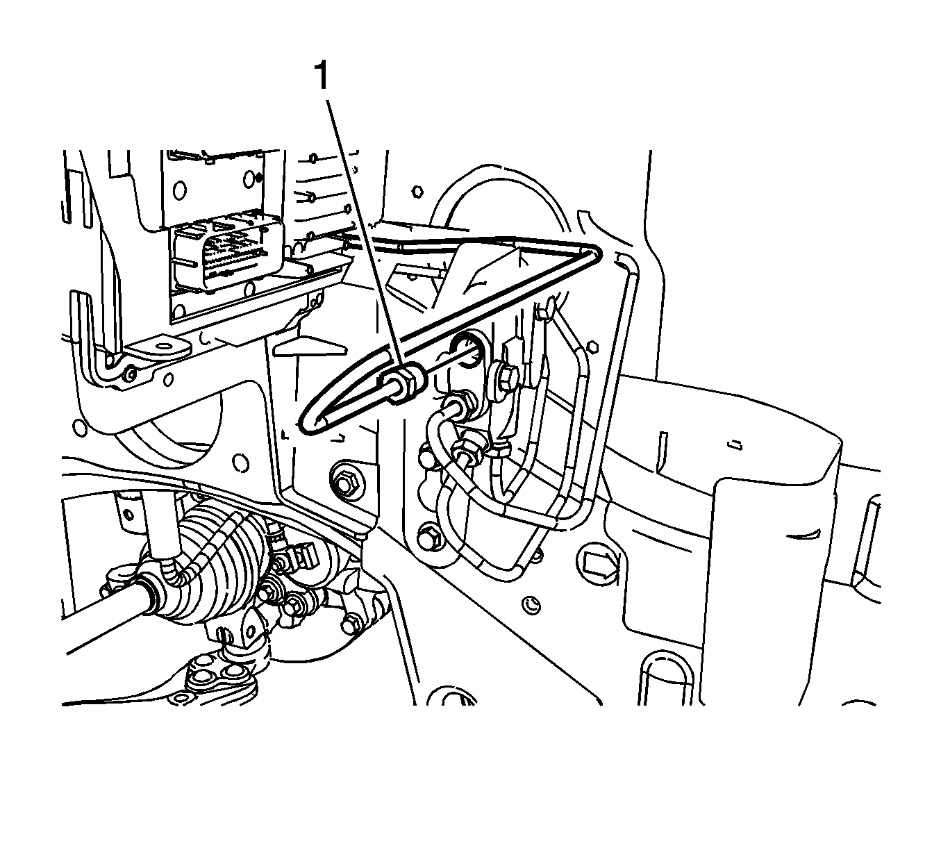
- Disconnect the LR brake pipe fitting (1).
- Disconnect the RR brake pipe fitting (1).
- Disconnect the LF brake pipe fitting (1).
- Disconnect the brake master cylinder primary inlet brake pipe fitting (1).
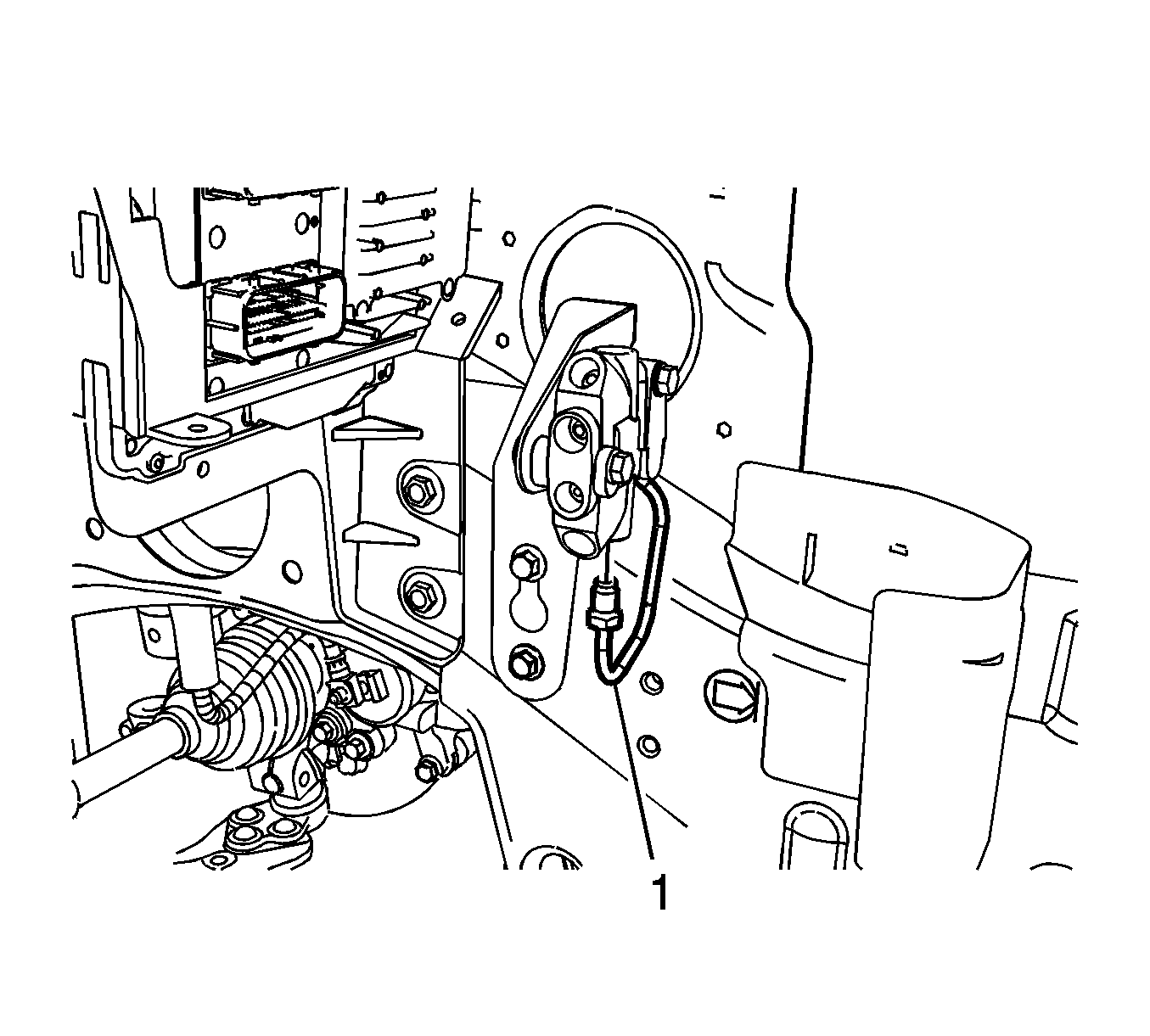
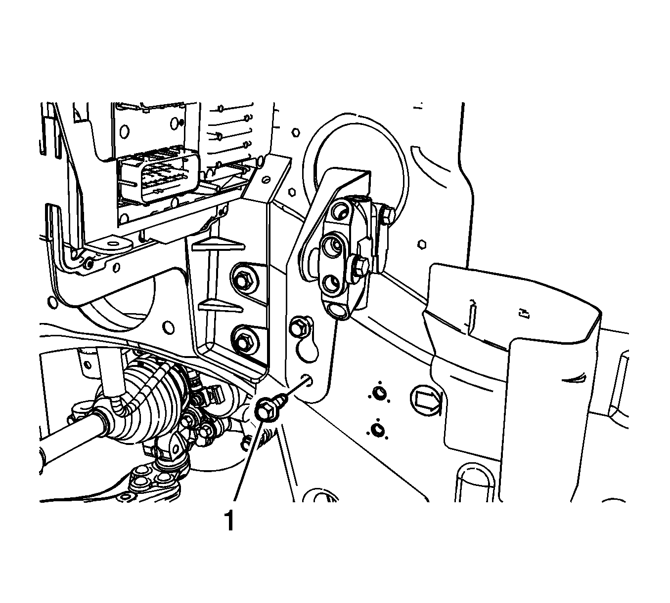
- Loosen, but do not remove, the upper proportioning valve bracket bolt (1).
- Remove the lower proportioning valve bracket bolt (1).
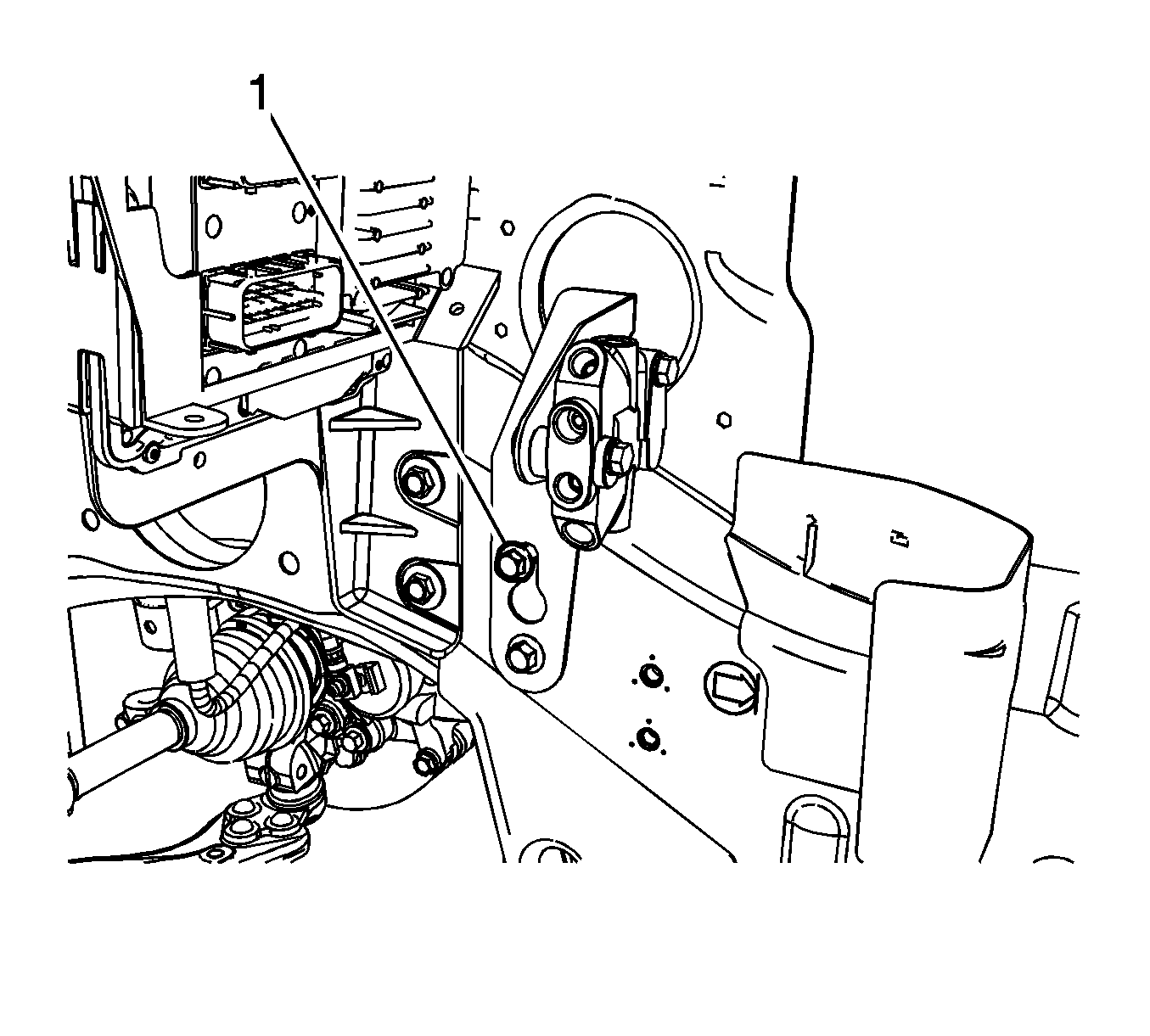
- Lift the proportioning valve and bracket assembly (1) and remove the assembly from the vehicle.
Cap the brake pipe fitting to prevent brake fluid loss and contamination.
Cap the brake pipe fitting to prevent brake fluid loss and contamination.
Cap the brake pipe fitting to prevent brake fluid loss and contamination.
Cap the brake pipe fitting to prevent brake fluid loss and contamination.
Cap the brake pipe fitting to prevent brake fluid loss and contamination.
Cap the brake pipe fitting to prevent brake fluid loss and contamination.
Installation Procedure
- Install the proportioning valve and bracket assembly (1) to the vehicle.
- Install the lower proportioning valve bracket bolt (1) and tighten to 25 N·m (18 lb ft).
- Tighten the upper proportioning valve bracket bolt (1) to 25 N·m (18 lb ft).
- Connect the brake master cylinder primary inlet brake pipe fitting (1) and tighten to 21 N·m (15 lb ft).
- Connect the LF brake pipe fitting (1) and tighten to 21 N·m (15 lb ft).
- Connect the RR brake pipe fitting (1) and tighten to 21 N·m (15 lb ft).
- Connect the LR brake pipe fitting (1) and tighten to 21 N·m (15 lb ft).
- Connect the RF brake pipe fitting (1) and tighten to 21 N·m (15 lb ft).
- Connect the brake master cylinder secondary inlet brake pipe fitting (1) and tighten to 21 N·m (15 lb ft).
- Install the ECM cover (1).
- Bleed the hydraulic brake system. Refer to Hydraulic Brake System Bleeding.
Caution: Refer to Fastener Caution in the Preface section.
