For 1990-2009 cars only
Removal Procedure
- Disconnect the battery negative cable. Refer to Battery Negative Cable Disconnection and Connection.
- Apply and release the brake pedal several times until it becomes firm to deplete the brake booster vacuum reserve.
- Disconnect the vacuum power brake vacuum sensor electrical connector, if equipped.
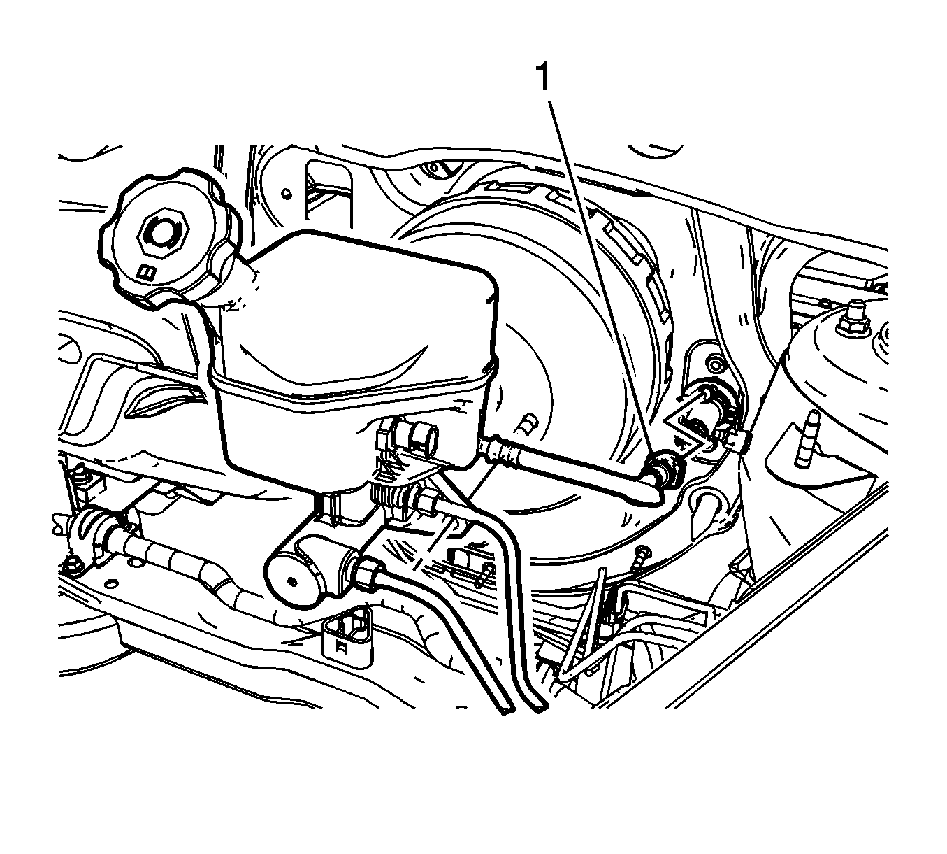
- Remove the vacuum power brake booster check valve and hose assembly from the brake booster grommet.
- Without disconnecting the wiring harness connectors, reposition the electrical center and the powertrain control modules from the underhood electrical center bracket and remove the bracket. Refer to Underhood Electrical Center or Junction Block Bracket Replacement.
- Disconnect the brake fluid level indicator switch electrical connector.
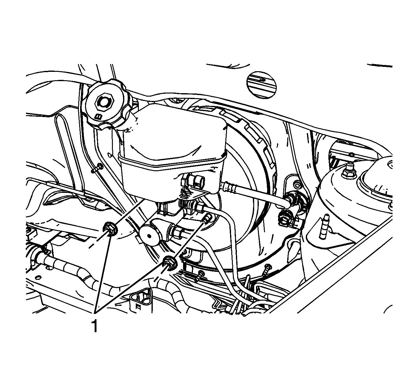
- Remove the master cylinder nuts (1).
- Disconnect the master cylinder clutch hose quick connect (1) from the clutch master cylinder, if equipped.
- Without disconnecting the brake pipe fittings, remove and position aside the master cylinder and support with heavy mechanics wire or equivalent.
- Remove the instrument panel (I/P) insulator. Refer to Instrument Panel Insulator Replacement.
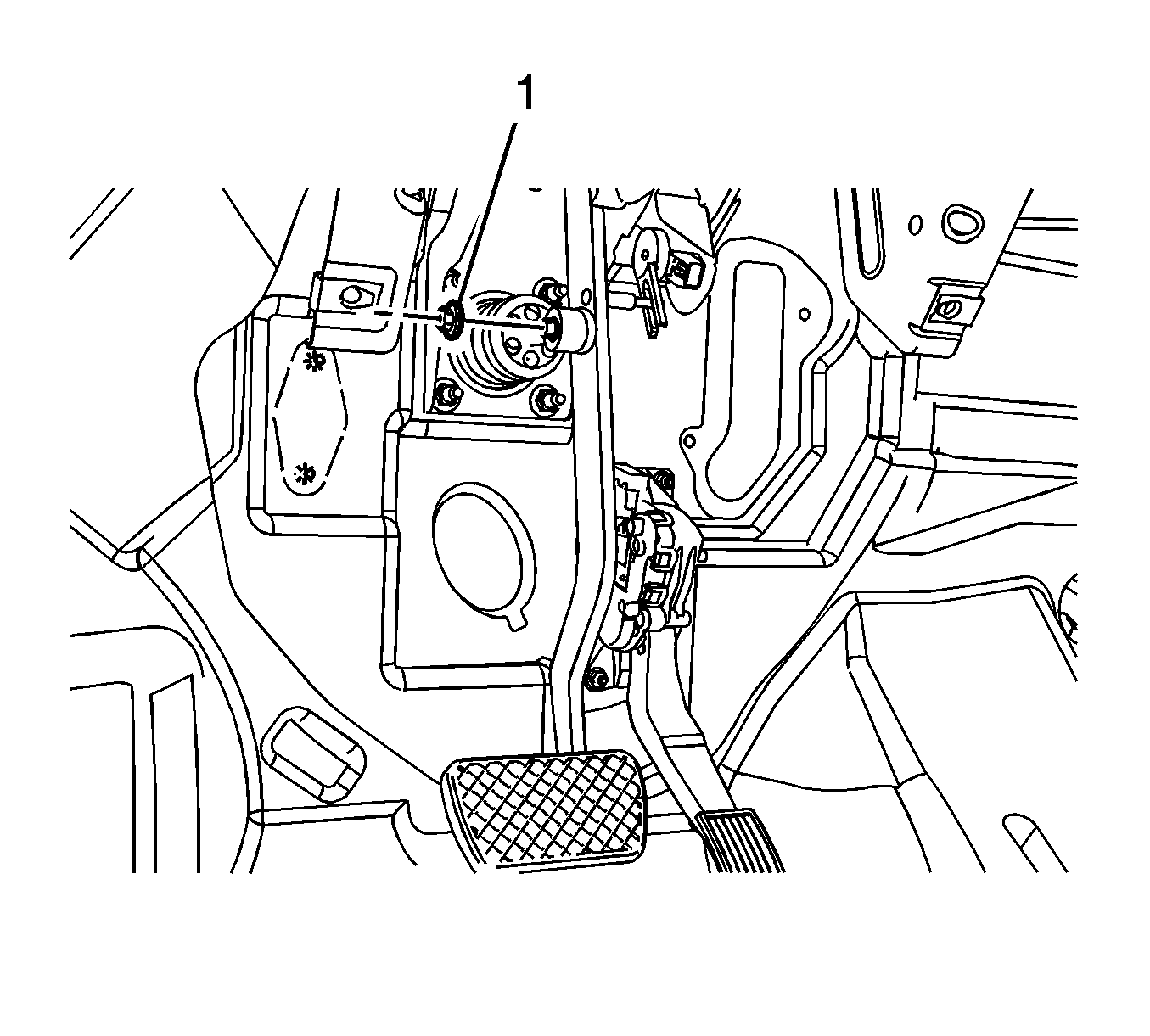
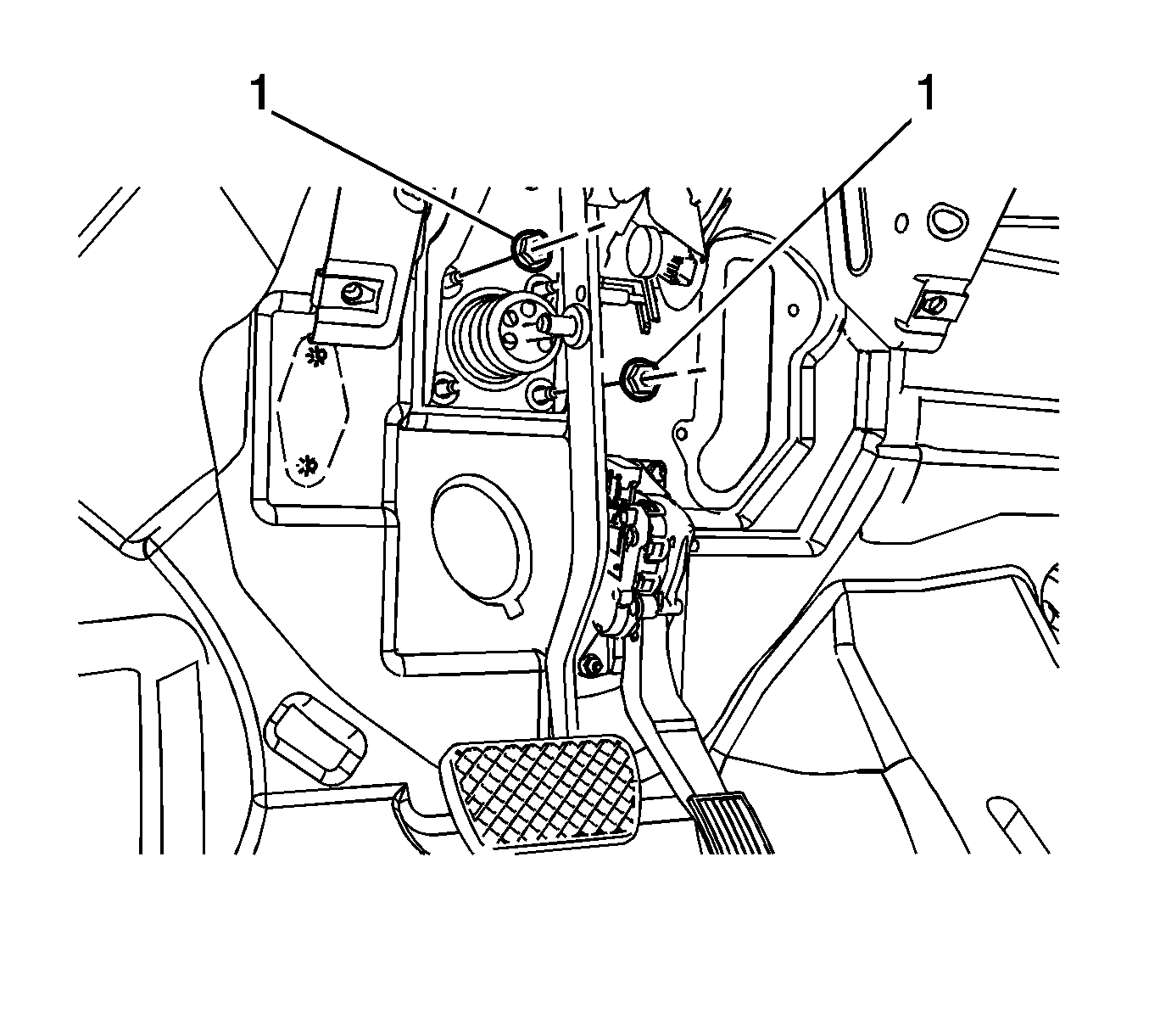
- Remove the brake pedal pushrod nut (1).
- Remove the brake pedal pushrod washer (1).
- Remove the brake pedal pushrod from the brake pedal pivot pin.
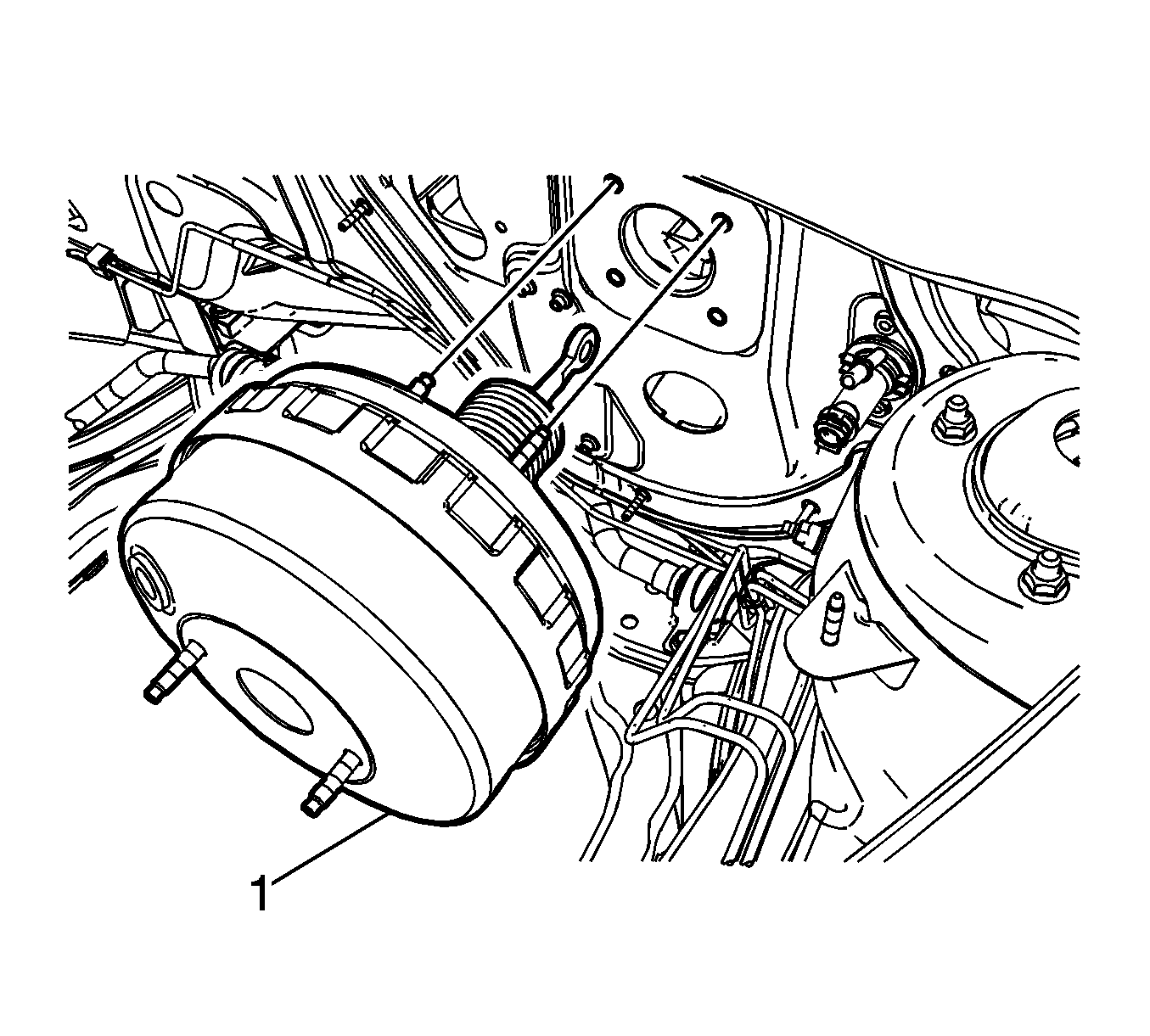
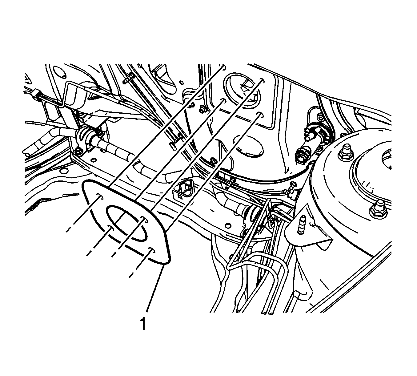
- Remove the vacuum brake booster nuts (1).
- Remove the power brake vacuum booster (1).
- Remove the power brake vacuum booster gasket (1).
Plug the master cylinder clutch hose outlet and cap the clutch master cylinder inlet port to prevent brake fluid loss and contamination.
Inspect the power brake vacuum booster gasket for damage and replace if necessary.
Installation Procedure
- Install the power brake vacuum booster gasket (1).
- Install the power brake vacuum booster (1).
- Install the vacuum brake booster nuts (1) and tighten to 22 N·m (16 lb ft).
- Apply a thin coating of high temperature grease GM P/N 12345996 (Canadian P/N 10953501) to the pushrod pin on the brake pedal.
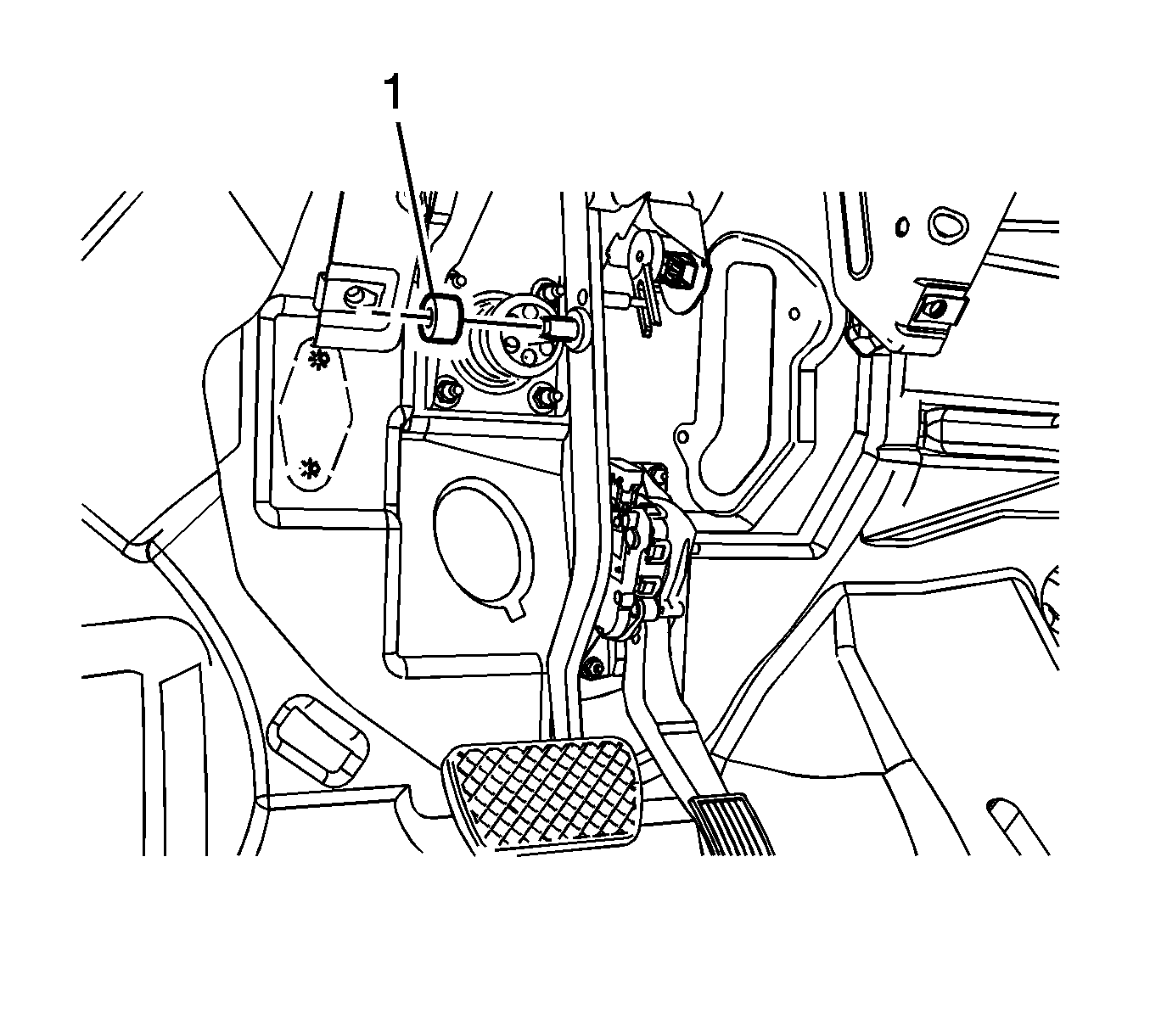
- Connect the brake pedal pushrod to the brake pedal pivot pin.
- Install the brake pedal pushrod washer (1).
- Install the brake pedal pushrod nut (1) and tighten to 10 N·m (89 lb in).
- Install the I/P insulator. Refer to Instrument Panel Insulator Replacement.
- Inspect the master cylinder seal (1) for damage and replace if necessary.
- Position the master cylinder to the power vacuum brake booster.
- Connect the master cylinder clutch hose quick connect (1) to the clutch master cylinder, if equipped.
- Install the master cylinder nuts (1) and tighten to 22 N·m (16 lb ft).
- Install the vacuum power brake booster check valve and hose assembly to the brake booster grommet.
- Connect the vacuum power brake vacuum sensor electrical connector, if equipped.
- Connect the brake fluid level indicator switch electrical connector.
- Position the electrical center and the powertrain control modules to the underhood electrical center bracket and install the bracket. Refer to Underhood Electrical Center or Junction Block Bracket Replacement.
- Connect the battery negative cable. Refer to Battery Negative Cable Disconnection and Connection.
Caution: Refer to Fastener Caution in the Preface section.
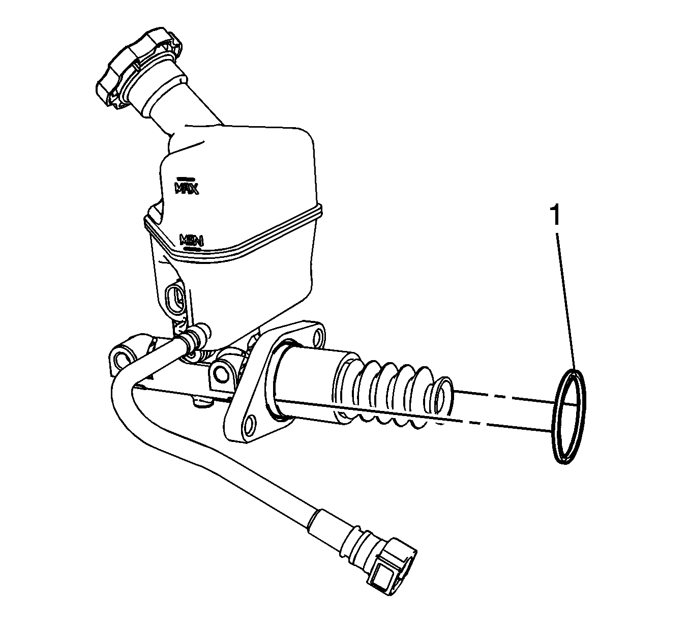
Ensure the master cylinder seal is properly seated in the groove in the master cylinder body.
If necessary, a small amount of denatured alcohol can be used as an assembly aid for installing the check valve and hose assembly to the vacuum booster grommet. Do not use soap.
