For 1990-2009 cars only
Warning: Refer to Brake Fluid Irritant Warning in the Preface section.
Caution: Refer to Brake Fluid Effects on Paint and Electrical Components Caution in the Preface section.
Removal Procedure
- Apply and release the brake pedal several times until the brake pedal becomes firm to deplete the brake booster vacuum reserve.
- Disconnect the battery negative cable. Refer to Battery Negative Cable Disconnection and Connection.
- Without disconnecting the wiring harness connectors, reposition the electrical center and the powertrain control modules from the underhood electrical center bracket and remove the bracket. Refer to Underhood Electrical Center or Junction Block Bracket Replacement.
- Disconnect the brake fluid level indicator switch electrical connector.
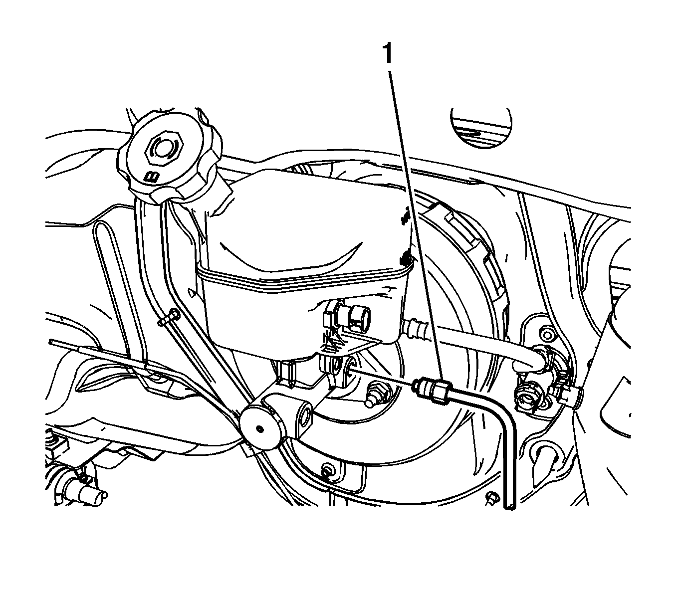
- Disconnect the master cylinder secondary brake pipe fitting (1).
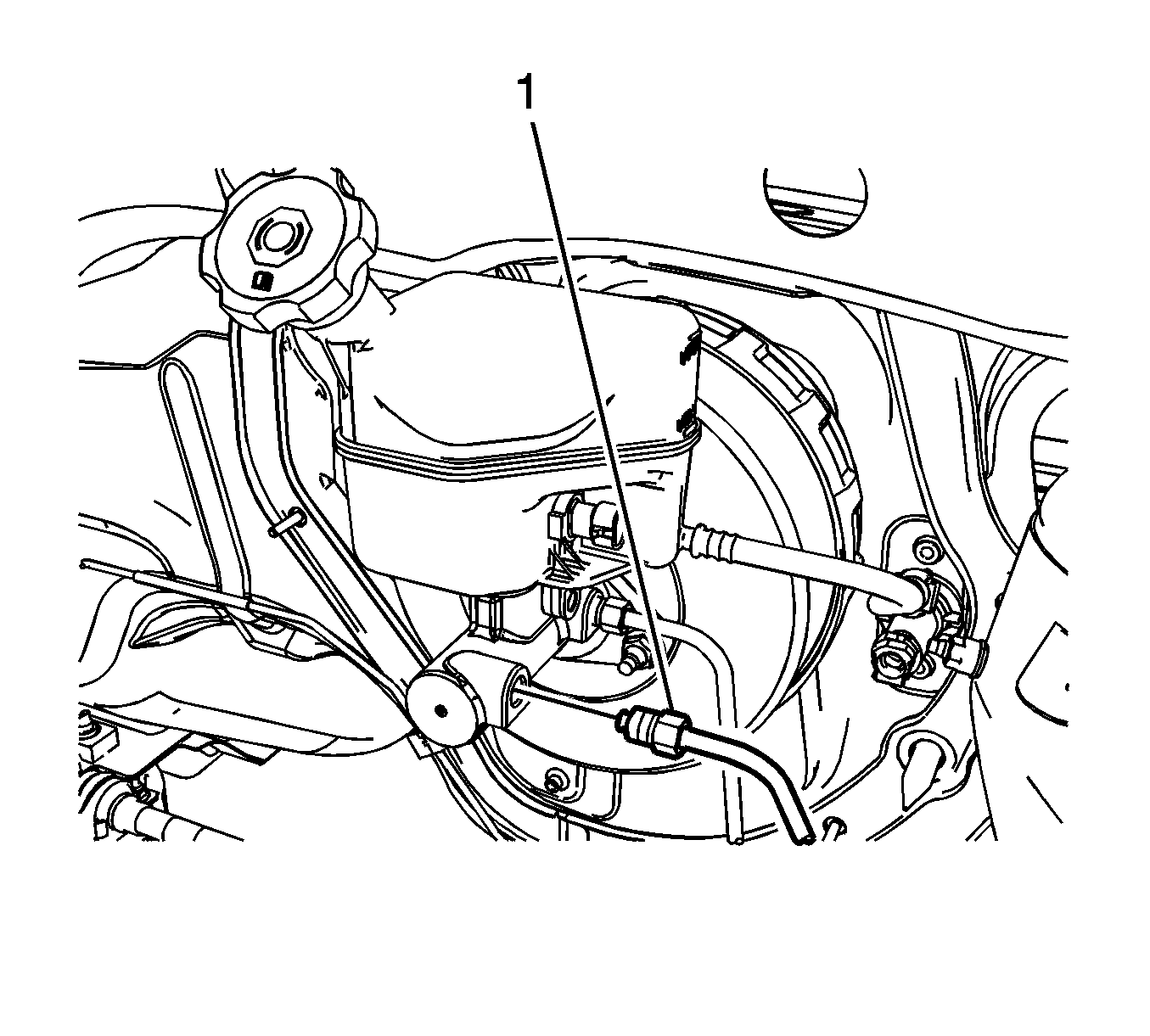
- Disconnect the master cylinder primary brake pipe fitting (1).
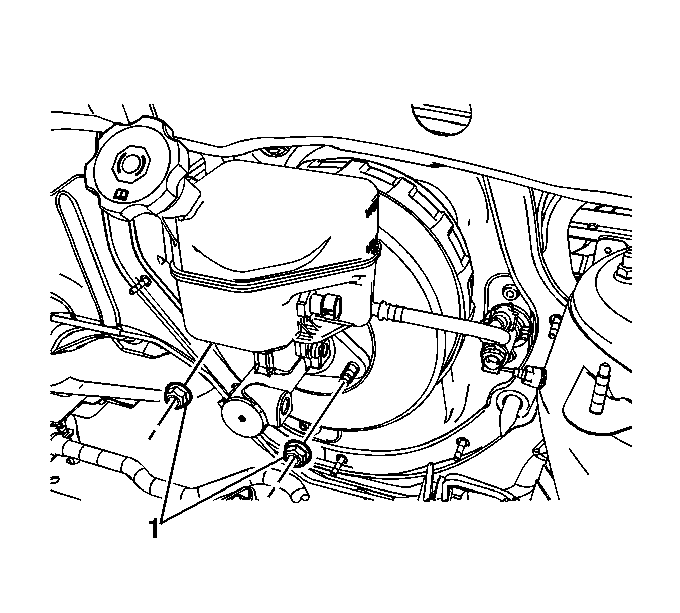
- Remove the brake master cylinder nuts (1).
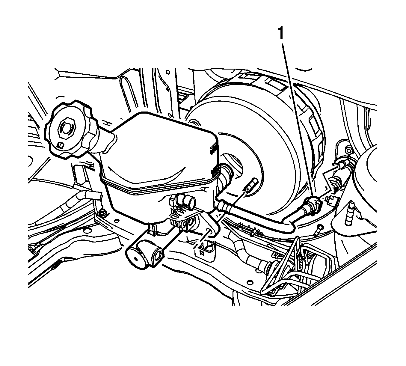
- Disconnect the master cylinder clutch hose quick connect fitting (1) from the clutch master cylinder, if equipped.
- Remove the master cylinder.
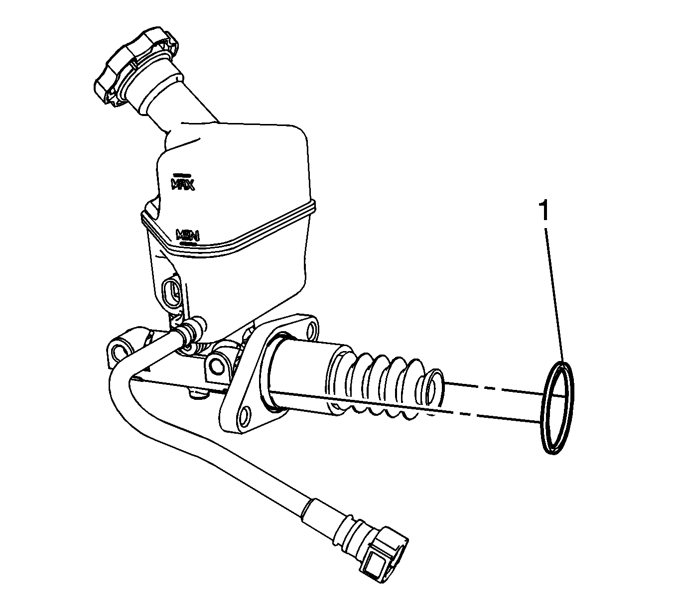
- Remove the master cylinder to vacuum brake booster seal (1) from the master cylinder.
Cap the brake pipe fitting and plug the master cylinder outlet port to prevent brake fluid loss and contamination.
Cap the brake pipe fitting and plug the master cylinder outlet port to prevent brake fluid loss and contamination.
Plug the master cylinder clutch hose and cap the clutch master cylinder inlet port to prevent brake fluid loss and contamination.
Installation Procedure
- Bench bleed the master cylinder. Refer to Master Cylinder Bench Bleeding.
- Install the master cylinder to vacuum brake booster seal (1) to the master cylinder.
- Position the master cylinder to the vacuum brake booster and connect the master cylinder clutch hose quick connect fitting (1) to the clutch master cylinder, if equipped.
- Install the brake master cylinder nuts (1) and tighten to 22 N·m (16 lb ft).
- Connect the master cylinder primary brake pipe fitting (1) and tighten to 21 N·m (15 lb ft).
- Connect the master cylinder secondary brake pipe fitting (1) and tighten to 21 N·m (15 lb ft).
- Install the underhood electrical center bracket and position the electrical center and the powertrain control modules to the electrical center bracket. Refer to Underhood Electrical Center or Junction Block Bracket Replacement.
- Connect the battery negative cable. Refer to Battery Negative Cable Disconnection and Connection.
- Bleed the hydraulic brake system. Refer to Hydraulic Brake System Bleeding.
Ensure the seal is fully seated in the groove in the master cylinder body.
Caution: Refer to Fastener Caution in the Preface section.
