Steering Gear Replacement LE8 and LE9
Special Tools
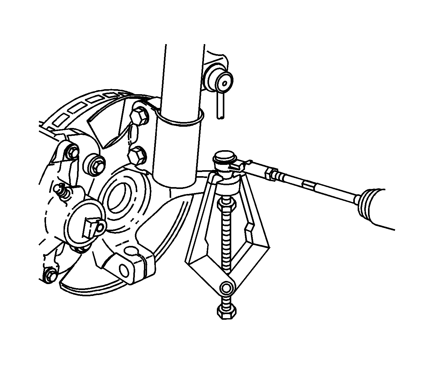
J 24319-B Steering Linkage and Tie Rod Puller
Removal Procedure
- Turn the steering wheel to the straight ahead position and lock it in place.
- Remove the front tire and wheel assemblies. Refer to Tire and Wheel Removal and Installation.
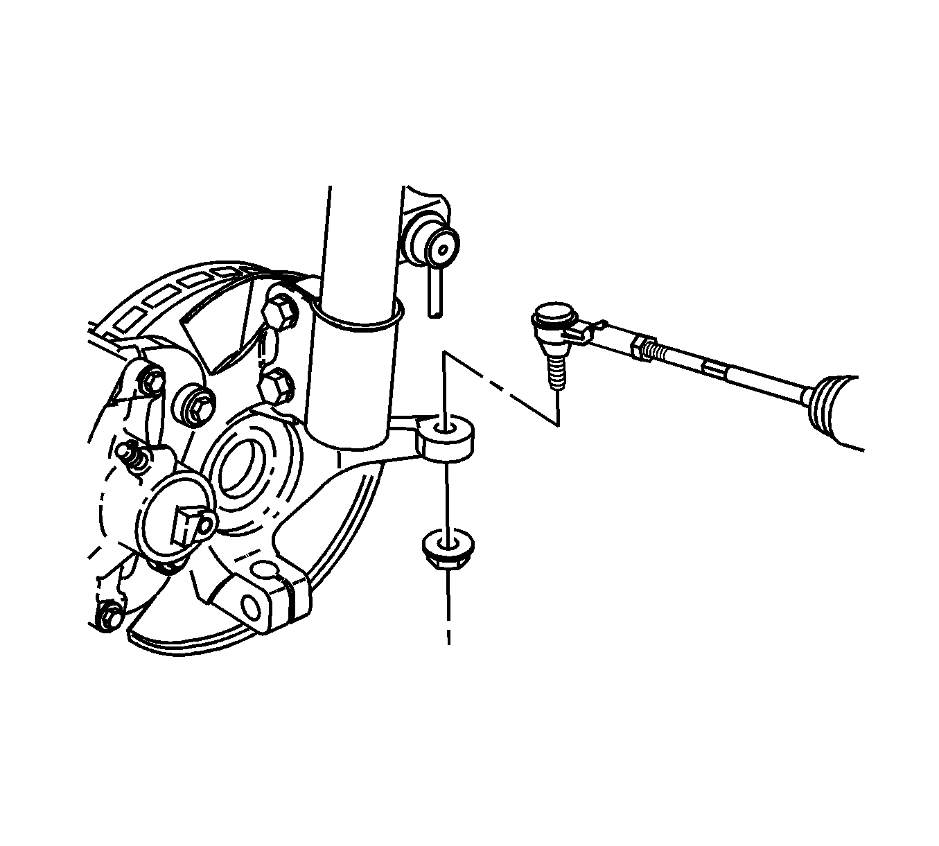
- Remove both rack and pinion outer tie rod end nuts and discard them.
- Use the J 24319-B Puller in order to separate the rack and pinion outer tie rod ends from the steering knuckles.
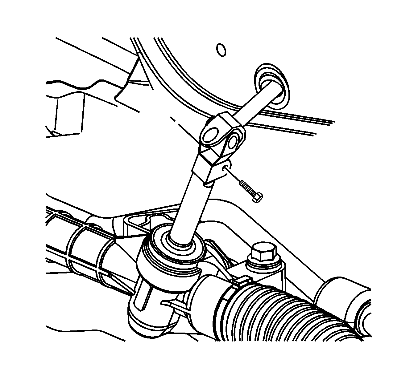
- Remove the intermediate steering shaft bolt at the steering gear and discard it.
- Separate the intermediate steering shaft from the steering gear.
- Remove the transmission rear mount. Refer to Transmission Rear Mount Replacement for the manual transaxle and Transmission Rear Mount Replacement for the automatic transaxle.
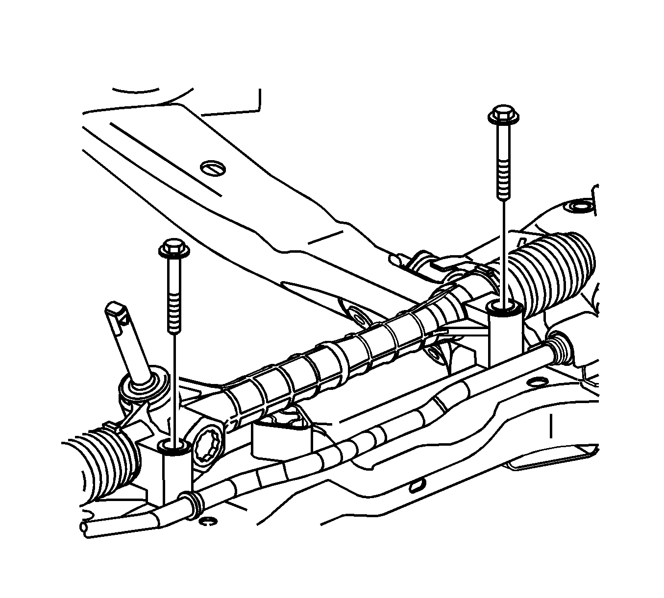
- Remove the steering gear bolts.
- Remove the steering gear from the vehicle through the left wheelhouse opening.
Caution: Secure the steering wheel utilizing a strap to prevent rotation. Locking of the steering column will prevent damage and a possible malfunction of the SIR system. The steering wheel must be secured
in position before disconnecting the following components:
• The steering column • The intermediate shaft • The steering gear


Note: Do not attempt to separate the rack and pinion outer tie rod ends using a wedge type tool.


Installation Procedure
- Position the steering gear in the vehicle through the left wheelhouse opening.
- Install the steering gear bolts and tighten to 110 N·m (81 lb ft).
- Install the transmission rear mount. Refer to Transmission Rear Mount Replacement for the manual transaxle and Transmission Rear Mount Replacement for the automatic transaxle.
- Connect the intermediate steering shaft to the steering gear.
- Install a new intermediate steering shaft bolt and tighten to 34 N·m (25 lb ft).
- Install the rack and pinion outer tie rod ends to the steering knuckles.
- Install new rack and pinion outer tie rod end nuts and tighten to 25 N·m (18 lb ft).
- Tighten the outer tie rod end nuts an additional 90 degrees.
- Install the front tire and wheel assemblies. Refer to Tire and Wheel Removal and Installation.
- Adjust the front toe. Refer to Wheel Alignment - Steering Wheel Angle and/or Front Toe Adjustment.
- If equipped with RPO JL4, calibrate the steering angle sensor. Refer to Control Module References.
Caution: Refer to Fastener Caution in the Preface section.


Steering Gear Replacement LNF
Special Tools
J 24319-B Steering Linkage and Tie Rod Puller
Removal Procedure
- Turn the steering wheel to the straight ahead position and lock it in place.
- Remove the front tire and wheel assemblies. Refer to Tire and Wheel Removal and Installation.
- Remove both rack and pinion outer tie rod end nuts and discard them.
- Use the J 24319-B Puller in order to separate the rack and pinion outer tie rod ends from the steering knuckles.
- Remove the intermediate steering shaft bolt at the steering gear and discard it.
- Separate the intermediate steering shaft from the steering gear.
- Remove the catalytic convertor. Refer to Catalytic Converter Replacement.
- Remove the transmission rear mount. Refer to Transmission Rear Mount Replacement for the manual transaxle and Transmission Rear Mount Replacement for the automatic transaxle.
- Remove the steering gear bolts.
- Remove the steering gear from the vehicle through the left wheelhouse opening.
Caution: Secure the steering wheel utilizing a strap to prevent rotation. Locking of the steering column will prevent damage and a possible malfunction of the SIR system. The steering wheel must be secured
in position before disconnecting the following components:
• The steering column • The intermediate shaft • The steering gear


Note: Do not attempt to separate the rack and pinion outer tie rod ends using a wedge type tool.


Installation Procedure
- Position the steering gear in the vehicle through the left wheelhouse opening.
- Install the steering gear bolts and tighten to 110 N·m (81 lb ft).
- Install the transmission rear mount. Refer to Transmission Rear Mount Replacement for the manual transaxle and Transmission Rear Mount Replacement for the automatic transaxle.
- Install the catalytic convertor. Refer to Catalytic Converter Replacement.
- Connect the intermediate steering shaft to the steering gear.
- Install a new intermediate steering shaft bolt and tighten to 34 N·m (25 lb ft).
- Install the rack and pinion outer tie rod ends to the steering knuckles.
- Install new rack and pinion outer tie rod end nuts and tighten to 25 N·m (18 lb ft).
- Tighten the outer tie rod end nuts an additional 90 degrees.
- Install the front tire and wheel assemblies. Refer to Tire and Wheel Removal and Installation.
- Adjust the front toe. Refer to Wheel Alignment - Steering Wheel Angle and/or Front Toe Adjustment.
- If equipped with RPO JL4, calibrate the steering angle sensor. Refer to Control Module References.
Caution: Refer to Fastener Caution in the Preface section.


