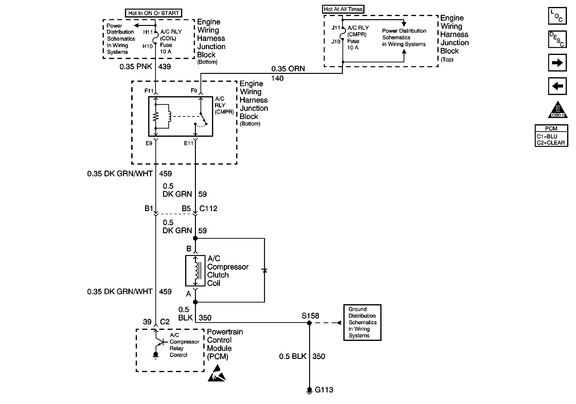
Refer to Engine Controls Schematics
A/C Compressor Controls

.
Circuit Description
When A/C is selected through the HVAC controller, a 12 volt signal is
supplied to the body control module (BCM). The BCM in turn signals the powertrain
control module (PCM) through the Class 2 serial data circuit that A/C has been
requested. The PCM then determines if conditions suitable for A/C operation are present.
If the PCM determines that the engine operating conditions are within the acceptable
ranges, the PCM will enable the A/C relay. The PCM provides a ground path for the
A/C relay coil. This action closes that A/C compressor relay contacts and B+ voltage
is supplied to the compressor clutch coil. The compressor clutch coil has its own
ground path.
The PCM will enable the A/C unless any of the following conditions are met:
| • | The throttle position is more than 96 percent . |
| • | The A/C pressure is more than 472 psi (4.9 volts) or less
than 9 psi (0.1 volt) as determined by the A/C pressure sensor. |
| • | The ignition voltage is less than 10.0 volts. |
| • | The engine is speed more than 4700 RPM. |
| • | The engine coolant temperature (ECT) is more than 124°C (255°F). |
| • | The intake air temperature (IAT) is less than 5°C (41°F). |
| • | A Class 2 communication error occurs between the HVAC
controller and the PCM. |
Diagnostic Aids
Check for the following conditions:
| • | Poor connection at the PCM -- Inspect harness connectors for the
following conditions: |
| - | Improperly formed or damaged terminals |
| - | Poor terminal to wire connection |
| • | Damaged harness -- Inspect the wiring harness for damage. |
| • | If the harness appears to be OK, disconnect the PCM, turn ON the ignition
and observe a Digital Multimeter connected to the A/C relay control circuit
at the PCM harness connector while moving connectors and wiring harnesses
related to the A/C relay. A change in voltage will indicate the location
of the malfunction. |
Check for conditions that will disable A/C operation:
| • | Throttle angle is more than 96 percent. |
| • | A/C head pressure is more than 440 psi (4.6 volts) or less
than 32 psi (0.3 volt) as determined by the A/C refrigerant
pressure sensor. |
| • | Ignition 1 voltage is below 10 volts. |
| • | Engine speed is greater then 4400 RPM for any amount of time. |
| • | ECT is more than 124°C (255°F). |
| • | IAT is less than 5°C (41°F). |

