GM Service Manual Online
For 1990-2009 cars only
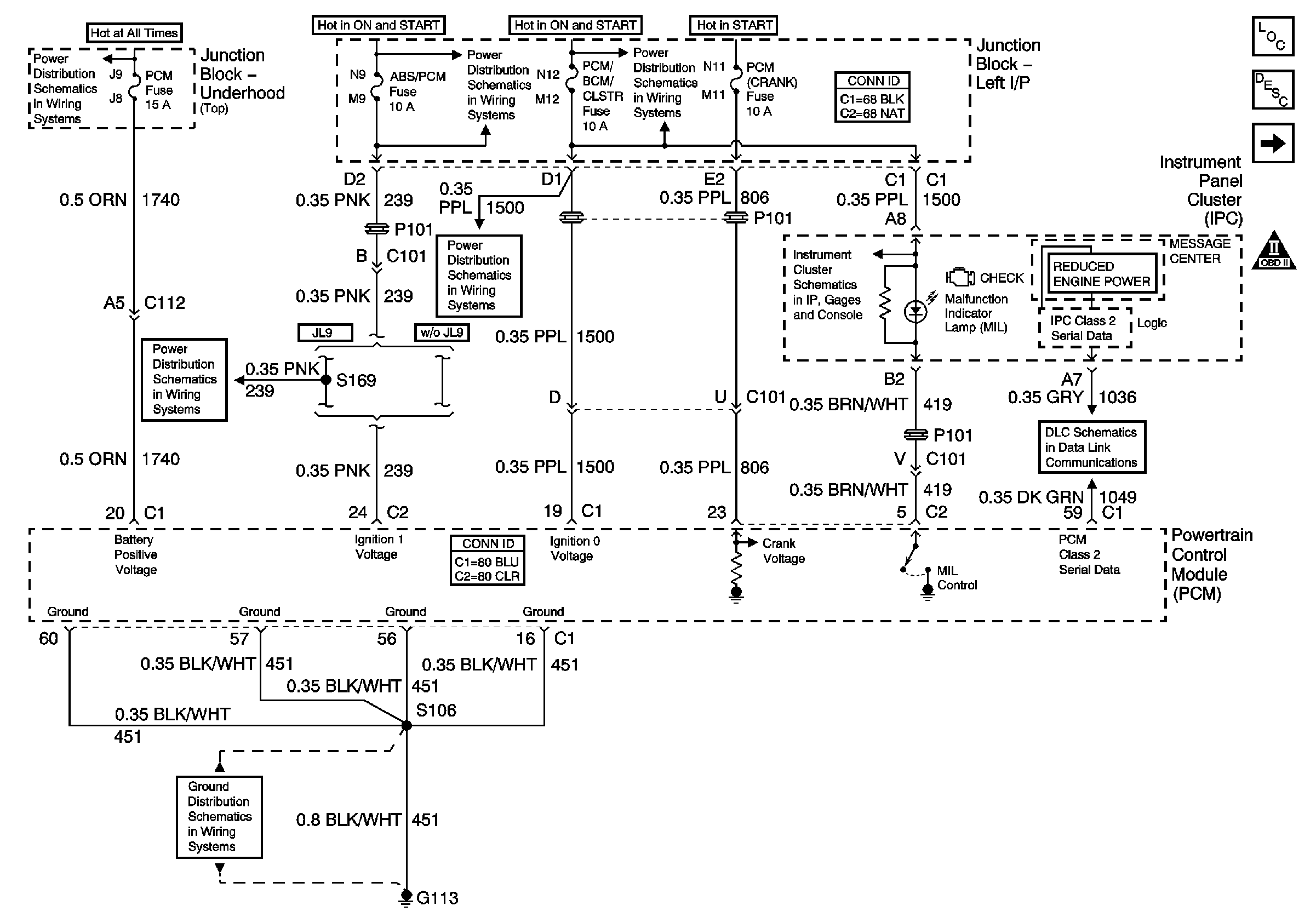
Figure 1:

Data Link, Grounds, MIL, and Power


Object Number: 796877  Size: FS
Master Electrical Component List
Powertrain Control Module Description
5 Volt and Low Reference Bussing
Engine Controls Schematic Icons
Junction Block-Underhood (Top) Bussing
A/C/CRUISE, A/C FAN, CRUISE, PCM/BCM/CLSTR, and PCM (CRANK) Fuses
ABS/PCM, SRS, STOP, and TURN SIGNAL Fuses
A/C/CRUISE, A/C FAN, CRUISE, PCM/BCM/CLSTR, and PCM (CRANK) Fuses
Ground, Odometer/PRNDL, Power, and VSS
DLC Schematics
G113 (2 of 2)
ABS/PCM, SRS, STOP, and TURN SIGNAL Fuses
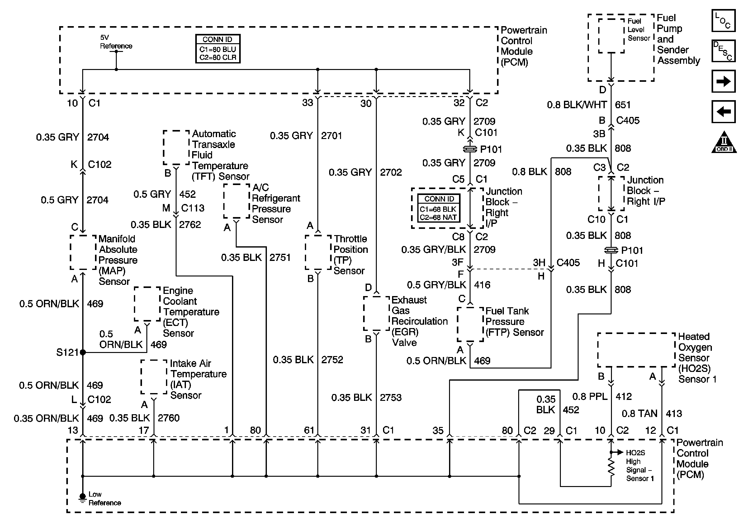
Figure 2:

5 Volt and Low Reference Bussing


Object Number: 785441  Size: FS
Master Electrical Component List
Powertrain Control Module Description
ECT, IAT, MAP, and TP Sensors
Data Link, Grounds, MIL, and Power
Engine Controls Schematic Icons
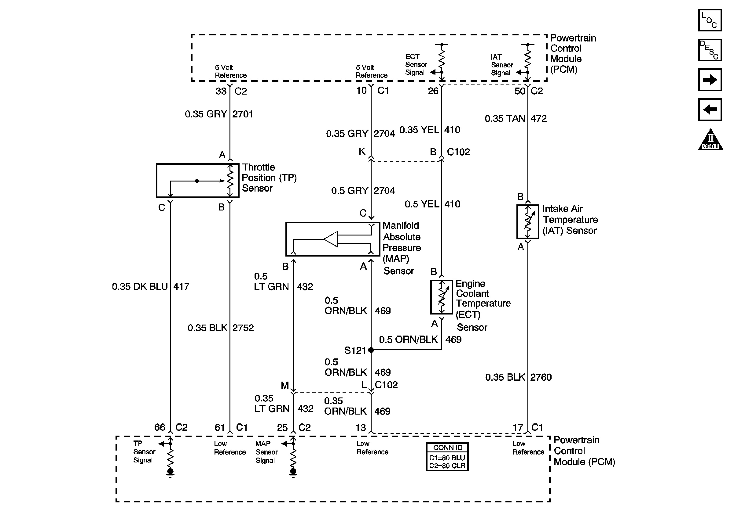
Figure 3:

ECT, IAT, MAP, and TP Sensors


Object Number: 784624  Size: FS
Master Electrical Component List
Air Intake System Description
MAF and VSS
5 Volt and Low Reference Bussing
Engine Controls Schematic Icons
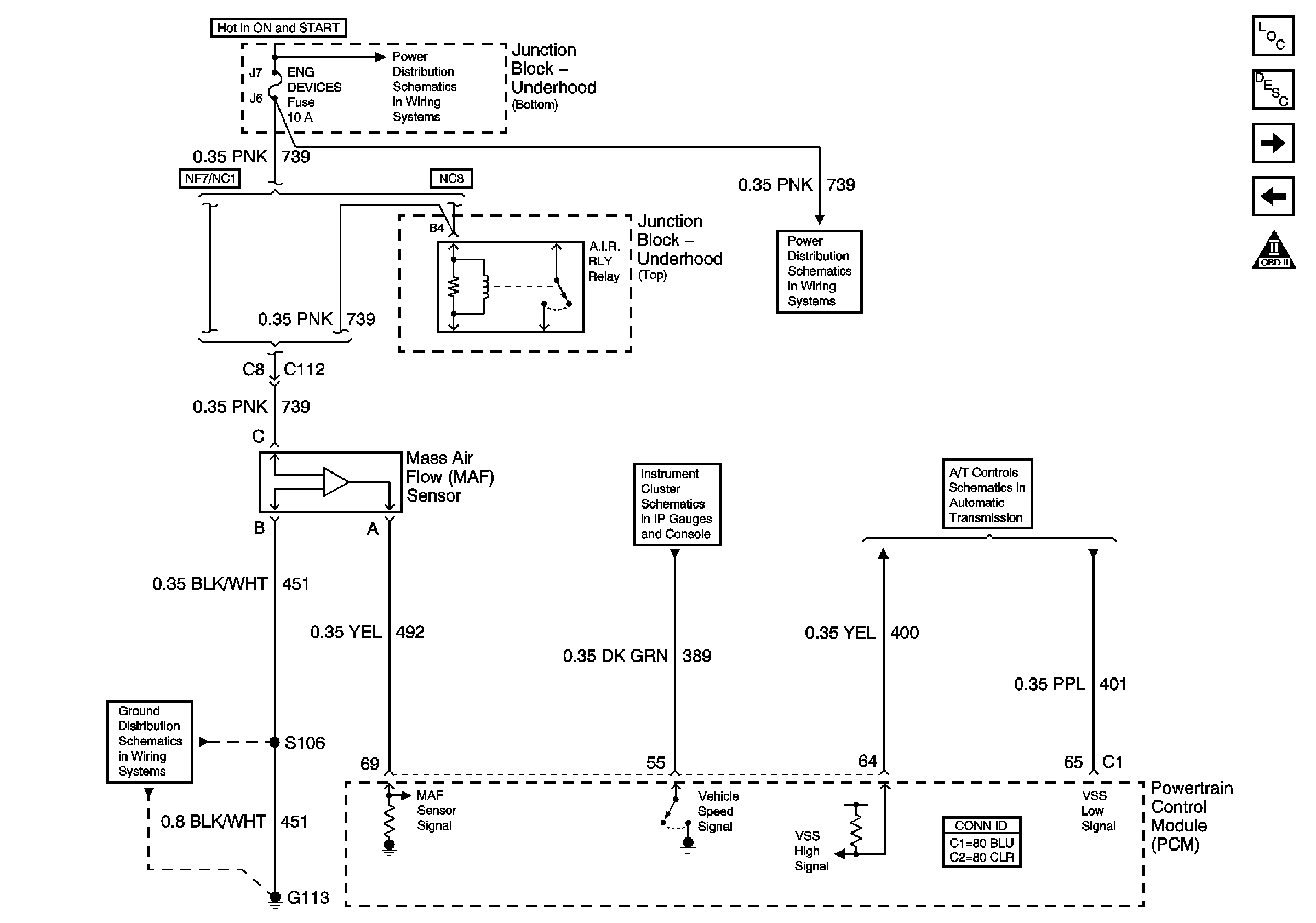
Figure 4:

MAF and VSS


Object Number: 784625  Size: FS
Master Electrical Component List
Air Intake System Description
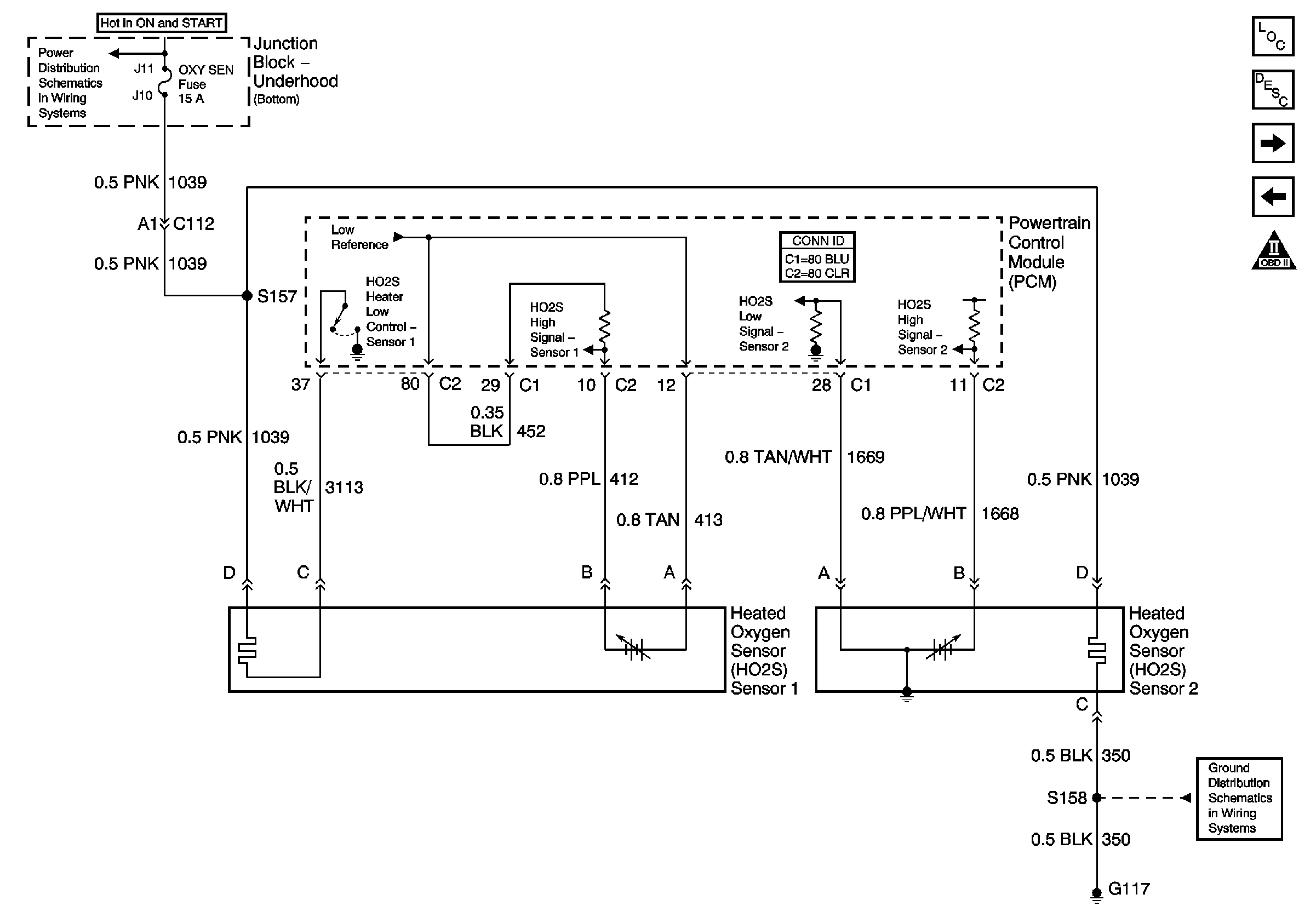
HO2S
ECT, IAT, MAP, and TP Sensors
Engine Controls Schematic Icons
DFI MDL, ENG DEVICES, and OXY SEN Fuses
G113 (2 of 2)
Ground, Odometer/PRNDL, Power, and VSS
ISS, Pressure Control, Switches, and VSS
Figure 5:

HO2S


Object Number: 784626  Size: FS
Master Electrical Component List
Fuel System Description
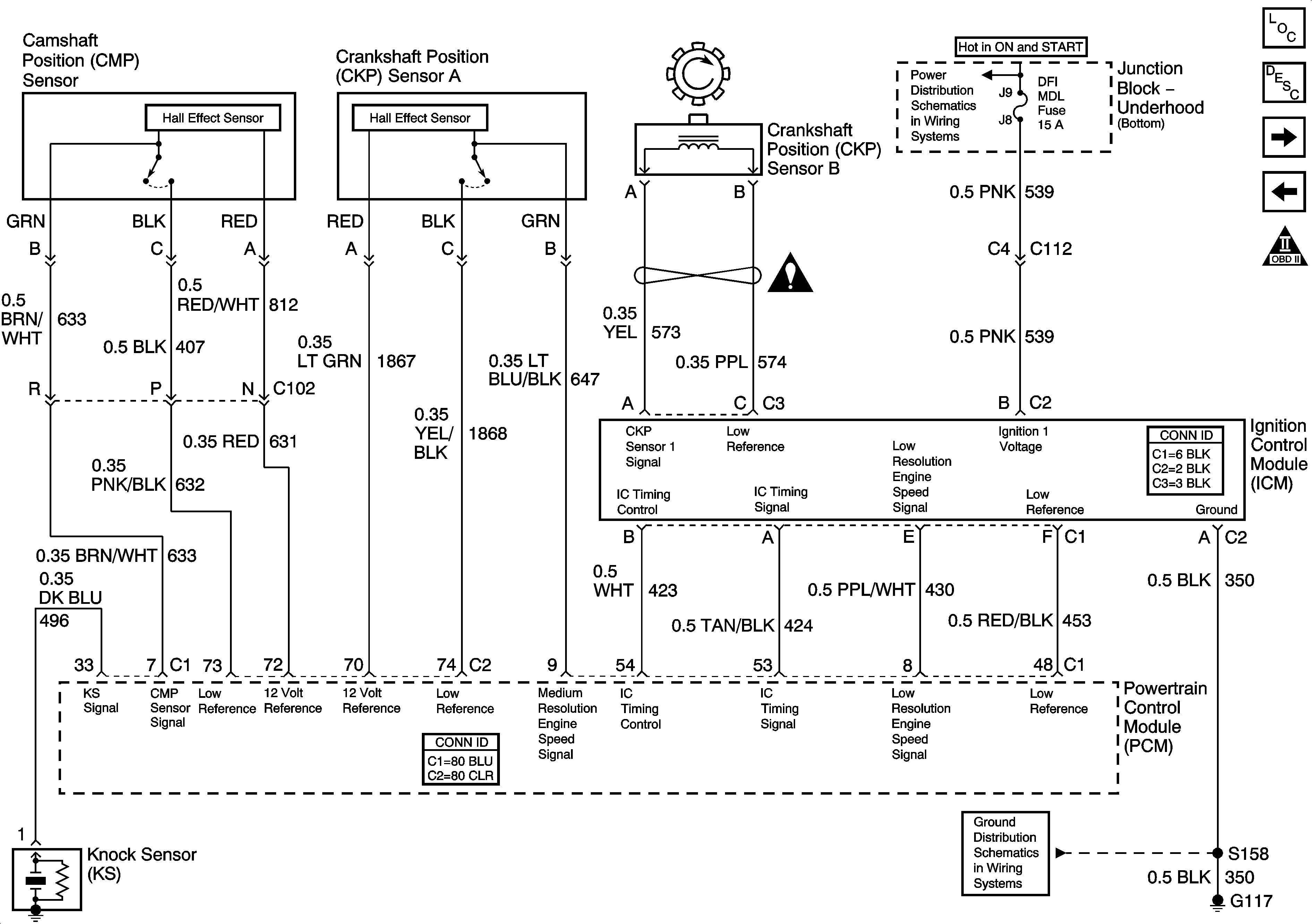
Ignition Controls
MAF and VSS
Engine Controls Schematic Icons
5 Volt and Low Reference Bussing
Junction Block - Underhood (Bottom) Bussing
G100, G111, G113 (1 of 2), G117, and G151
Figure 6:

Ignition Controls


Object Number: 1586836  Size: FS
Master Electrical Component List
Electronic Ignition (EI) System Description
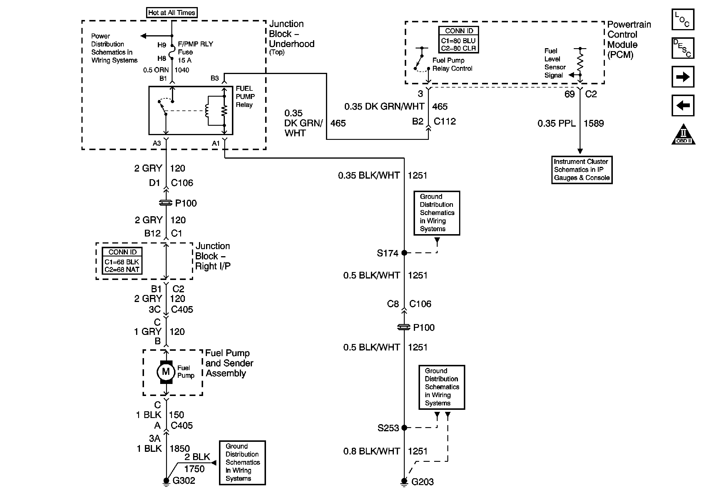
Fuel Pump
HO2S
Engine Controls Schematic Icons
Junction Block - Underhood (Bottom) Bussing
G100, G111, G113 (1 of 2), G117, and G151
Figure 7:

Fuel Pump


Object Number: 784627  Size: FS
Master Electrical Component List
Fuel System Description
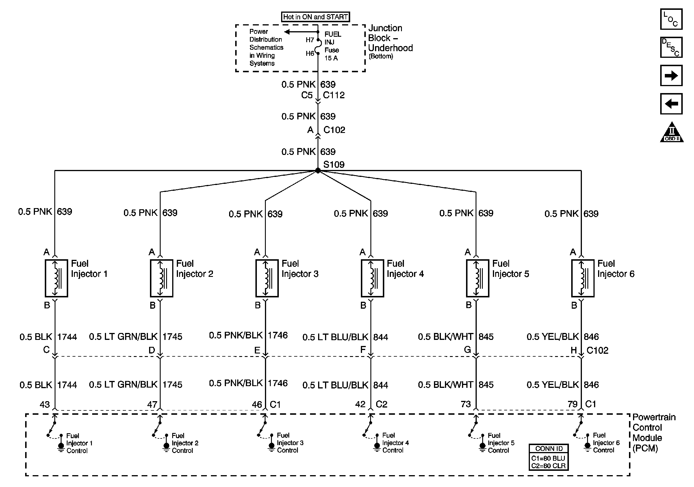
Fuel Injectors
Ignition Controls
Engine Controls Schematic Icons
Junction Block-Underhood (Top) Bussing
Gages, Illumination, and Indicators
G203 (3 of 3)
G203 (1 of 3)
G302 (1 of 2)
Figure 8:

Fuel Injectors


Object Number: 798540  Size: FS
Master Electrical Component List
Fuel System Description
EVAP and FTP
Fuel Pump
Engine Controls Schematic Icons
Junction Block - Underhood (Bottom) Bussing
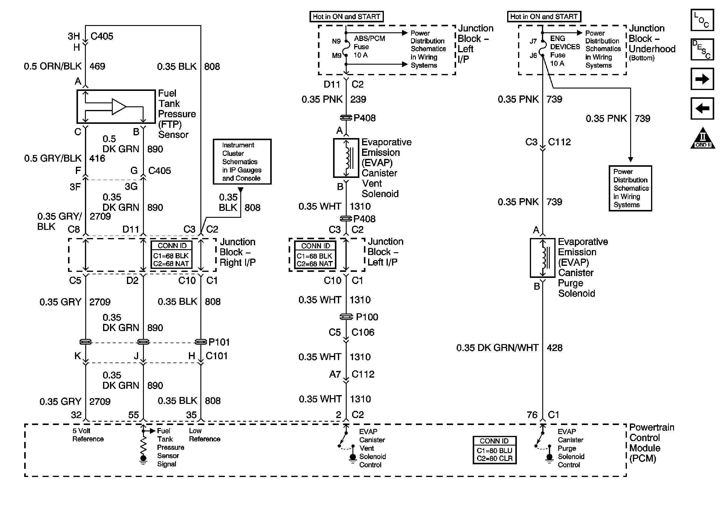
Figure 9:

EVAP and FTP


Object Number: 784628  Size: FS
Master Electrical Component List
Evaporative Emission Control System Description
AIR, EGR, and IAC
Fuel Injectors
Engine Controls Schematic Icons
ABS/PCM, SRS, STOP, and TURN SIGNAL Fuses
DFI MDL, ENG DEVICES, and OXY SEN Fuses
Gages, Illumination, and Indicators
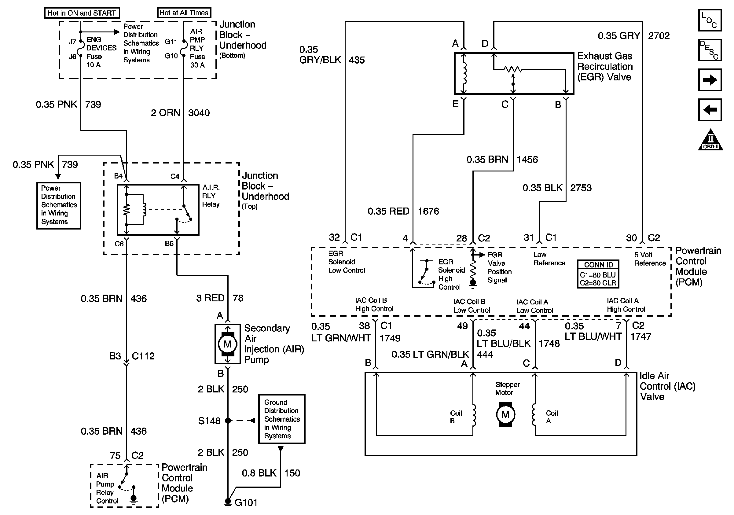
Figure 10:

AIR, EGR, and IAC


Object Number: 784629  Size: FS
Master Electrical Component List
Exhaust Gas Recirculation (EGR) System Description
Subsystem References
EVAP and FTP
Engine Controls Schematic Icons
Junction Block - Underhood (Bottom) Bussing
DFI MDL, ENG DEVICES, and OXY SEN Fuses
G101
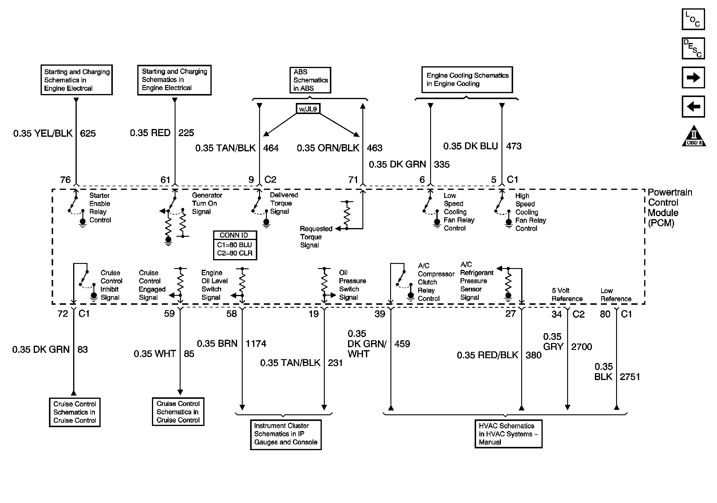
Figure 11:

Subsystem References


Object Number: 784630  Size: FS
Master Electrical Component List
Powertrain Control Module Description
A/T References
AIR, EGR, and IAC
Engine Controls Schematic Icons
Engine Cranking
Charging Control and Indicator
PCM and Stop Lamp Switch
Engine Cooling Schematics
Cruise Control - Monte Carlo
Indicator Control
Message Center
Compressor Control
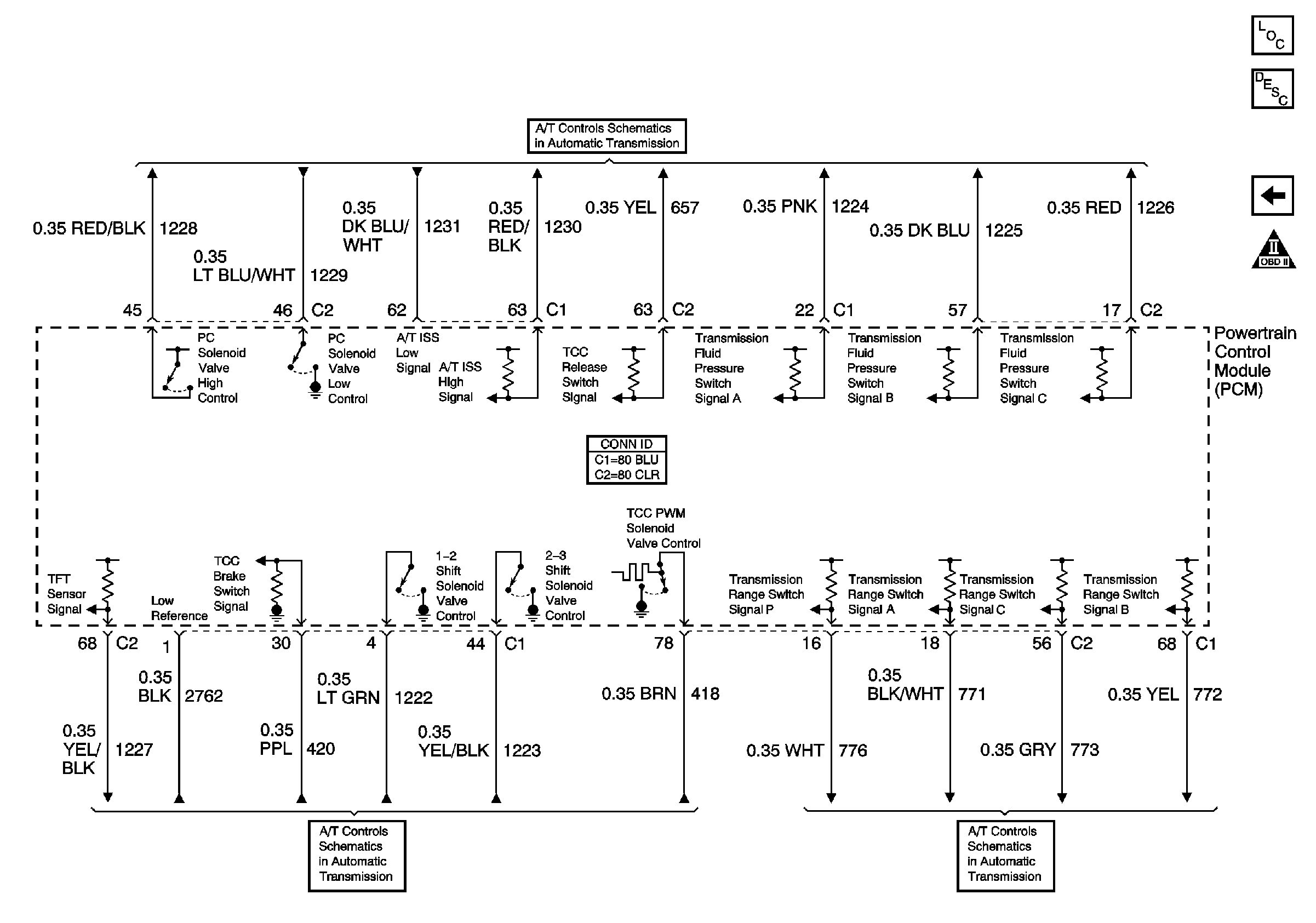
Figure 12:

A/T References


Object Number: 784631  Size: FS
Master Electrical Component List
Powertrain Control Module Description
Subsystem References
Engine Controls Schematic Icons
ISS, Pressure Control, Switches, and VSS
Solenoids, TCC, and TFT
PRNDL