Instrument Panel Cluster Trim Plate Bezel Replacement Impala
Removal Procedure
- Apply the parking brake.
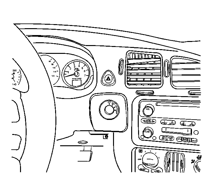
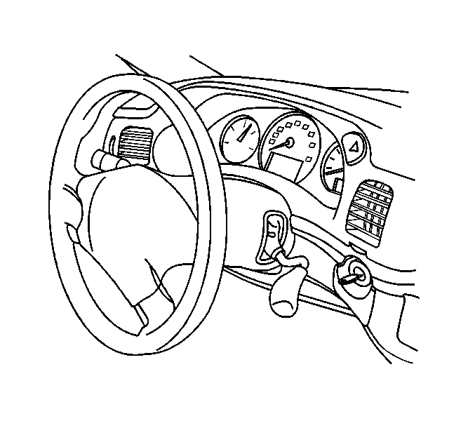
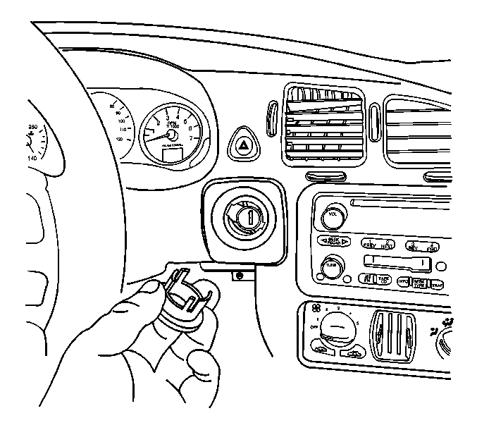
- Using a small flat-bladed tool, remove the bezel from the ignition switch cylinder.
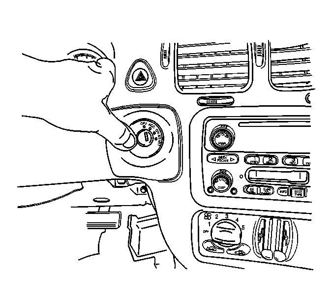
- If the vehicle is equipped with a column shift, position the transaxle shift control indicator to 1. Keep the key in the ignition switch cylinder.
- Adjust the steering wheel for access.
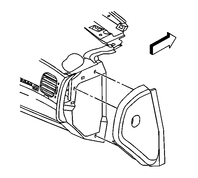
- Remove the access covers from the right and the left instrument panel (IP) fuse block, as required.
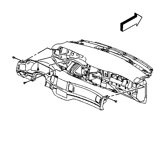
- Remove the screws from the IP cluster trim plate.
- Starting at the right end of the IP cluster, grasp the trim plate and pull rearward.
- Continue working around the IP cluster trim plate until all of the retainers are released from the IP trim pad.
- Disconnect the electrical connectors from the hazard switch and from the traction control switch, if equipped.
- Remove the IP cluster trim plate.
Installation Procedure
- Position the IP cluster trim plate to the IP trim pad.
- Connect the electrical connectors to the hazard switch and to the traction control switch, if equipped.
- Press the IP cluster trim plate into the IP trim pad until the retainers are fully seated.
- Install the IP cluster trim plate screws.
- Install the access covers to the right and the left IP fuse block, as required.
- Position the bezel retainers to the tabs on the ignition switch cylinder.
- Install the bezel to the ignition switch cylinder pressing into place until fully seated.
- Return the steering wheel to the original position.
- If the vehicle is equipped with a column shift, position the transaxle shift control indicator to Park and remove the key from the ignition switch cylinder.
- Release the parking brake.

Notice: Use the correct fastener in the correct location. Replacement fasteners must be the correct part number for that application. Fasteners requiring replacement or fasteners requiring the use of thread locking compound or sealant are identified in the service procedure. Do not use paints, lubricants, or corrosion inhibitors on fasteners or fastener joint surfaces unless specified. These coatings affect fastener torque and joint clamping force and may damage the fastener. Use the correct tightening sequence and specifications when installing fasteners in order to avoid damage to parts and systems.
Tighten
Tighten the screws to 2 N·m (18 lb in).


Instrument Panel Cluster Trim Plate Bezel Replacement Monte Carlo
Removal Procedure
- Adjust the steering wheel for access.
- Using a small flat-bladed tool, remove the bezel from the ignition switch cylinder.
- Remove the access cover from the left IP fuse block.
- Remove the steering column filler. Refer to Steering Column Opening Filler Replacement .
- Open the IP compartment door.
- Remove the screw from the left side of the IP cluster trim plate.
- Remove the screw from the right side of the IP cluster trim plate.
- If the vehicle is equipped with a front floor console, position the transaxle shift control lever to the rear most position.
- Remove the trim plate starting at the right side of the IP cluster and pulling rearward, continuing until all of the retainers are released.
- Disconnect the electrical connector from the hazard switch.
- Remove the IP cluster trim plate.

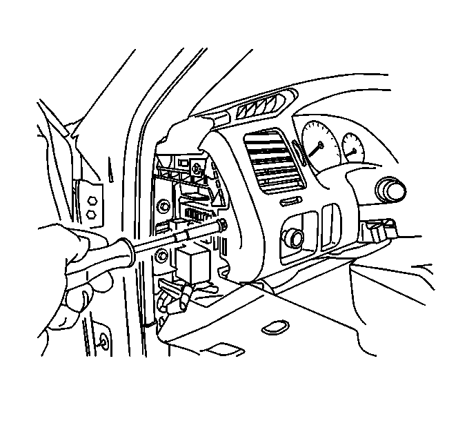
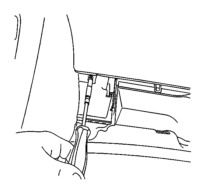
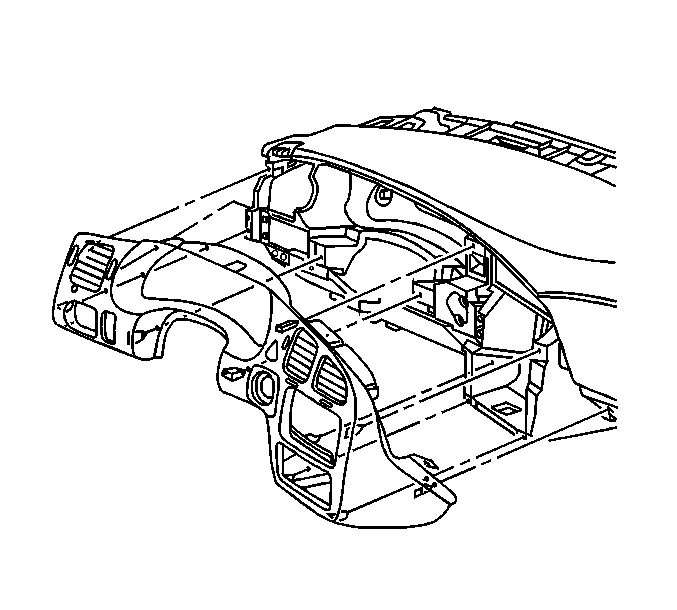
Important: Moderately twist the left side of the IP cluster trim plate in order to clear the cluster area from the instrument panel.
Installation Procedure
- Position the IP cluster trim plate to the IP trim pad.
- Connect the electrical connector to the hazard switch.
- Align the IP cluster trim plate retainers to the slots in the instrument panel.
- Install the IP cluster trim plate by pressing into place until the retainers are fully seated.
- Install the screw to the right side of the IP cluster trim plate.
- Install the screw to the left side of the IP cluster trim plate.
- Close the IP compartment door.
- Install the access cover to the left IP fuse block.
- Install the steering column filler. Refer to Steering Column Opening Filler Replacement .
- Position the bezel retainers to the tabs on the ignition switch cylinder.
- Install the bezel to the ignition switch cylinder by pressing into place until fully seated.
- If the vehicle is equipped with a front floor console, position the transaxle shift control lever to PARK position.
- Reposition the steering wheel to the original position.

Important: Moderately twist the left side of the instrument panel (IP) cluster trim plate in order to clear the cluster area from the instrument panel.

Notice: Use the correct fastener in the correct location. Replacement fasteners must be the correct part number for that application. Fasteners requiring replacement or fasteners requiring the use of thread locking compound or sealant are identified in the service procedure. Do not use paints, lubricants, or corrosion inhibitors on fasteners or fastener joint surfaces unless specified. These coatings affect fastener torque and joint clamping force and may damage the fastener. Use the correct tightening sequence and specifications when installing fasteners in order to avoid damage to parts and systems.
Tighten
Tighten the screw to 2 N·m (18 lb in).

Tighten
Tighten the screw to 2 N·m (18 lb in).


