Tools Required
| • | J 8001 Dial Indicator Set |
| • | J 21465-13 Drive Handle Extension |
| • | J 36660-A Torque Angle Meter |
| • | J 36996 Balance Shaft Installer |
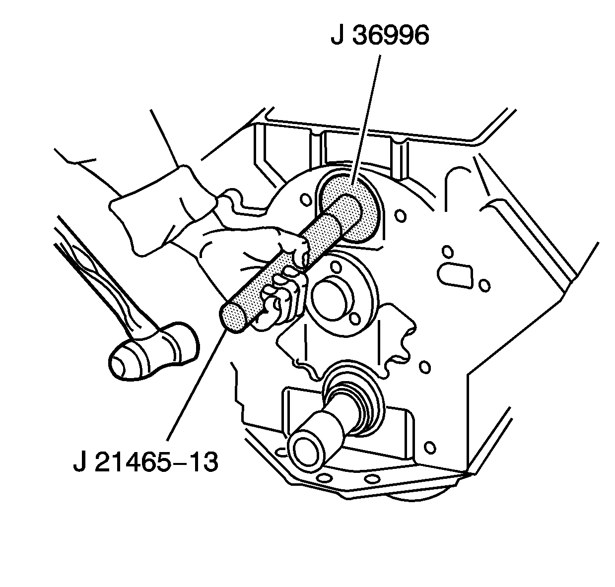
- Use J 21465-13 and J 36996 to install the balance shaft into the engine block.
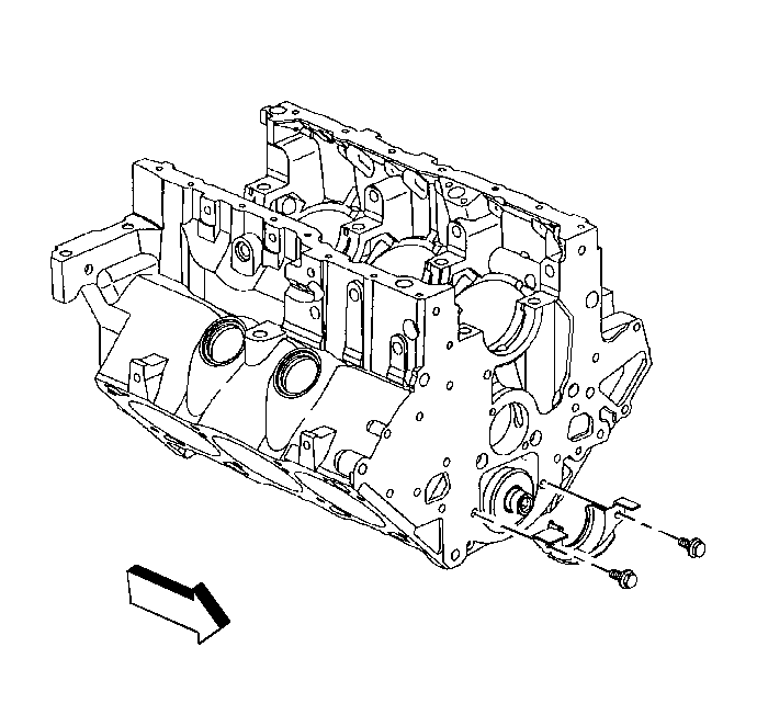
- Install the balance shaft retainer.
- Install the balance shaft retainer bolts.
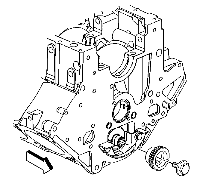
- Install the balance shaft driven gear.
- Install the balance shaft driven gear bolt.
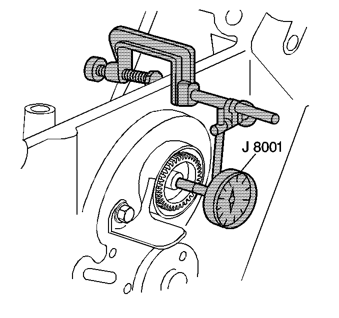
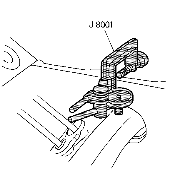
- Using J 8001 measure the balance shaft end play. End play must not exceed 0.028 mm (0.008 in).
- Using J 8001 measure the balance shaft radial play at the rear. Radial play must be between 0.0127-0.119 mm (0.0005-0.0047 in).
- Install the balance shaft drive gear.
- Install the camshaft sprocket.
- Turn the camshaft so the timing mark on the camshaft sprocket is straight down.
- Remove the camshaft sprocket and balance shaft drive gear.
- Turn the balance shaft so the timing mark on the balance shaft driven gear points straight down.
- Partially install the balance shaft drive gear so the gear teeth are not engaged.
- Align the marks on the balance shaft driven gear and the balance shaft drive gear. Do this by turning the balance shaft.
- Once marks are aligned, fully seat balance shaft drive gear and engage gear teeth.
- Turn the crankshaft so the number one piston is at top dead center.
- Install the timing chain and camshaft spocket.
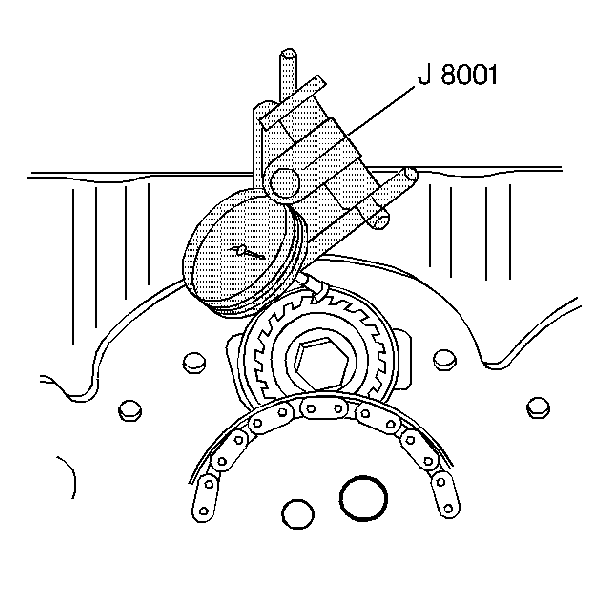
- Using J 8001 measure the gear lash at four places. Measure every quarter turn. Gear lash must be between 0.050-0.127 mm (0.002-0.005 in).
Notice: Use the correct fastener in the correct location. Replacement fasteners must be the correct part number for that application. Fasteners requiring replacement or fasteners requiring the use of thread locking compound or sealant are identified in the service procedure. Do not use paints, lubricants, or corrosion inhibitors on fasteners or fastener joint surfaces unless specified. These coatings affect fastener torque and joint clamping force and may damage the fastener. Use the correct tightening sequence and specifications when installing fasteners in order to avoid damage to parts and systems.
Tighten
Tighten the balance shaft retainer bolts to 30 N·m (22 lb ft).
Notice: Refer to Special Fastener Notice in the Preface section.
Tighten
Tighten the balance shaft driven gear bolt to 22 N·m (16 lb ft).
Use J 36660-A
to tighten
the bolt an additional 70 degrees.
