For 1990-2009 cars only
Removal Procedure
- Remove the left instrument panel (IP) insulator. Refer to Instrument Panel Insulator Panel Replacement - Left Side in Instrument Panel, Gages, and Console.
- Remove the IP knee bolster bracket. Refer to Driver Knee Bolster Bracket Replacement in Instrument Panel, Gages, and Console.
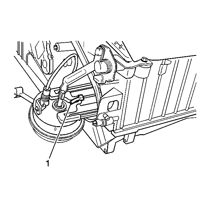
- Disconnect the support clip for the ignition switch harness.
- Disconnect the vacuum line from the mode actuator.
- Lift the lock tab up (1) to remove the actuator.
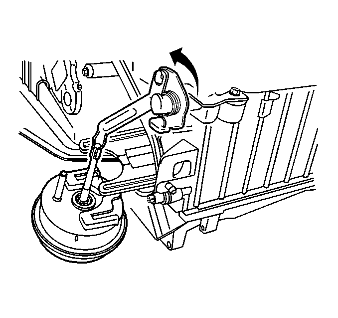
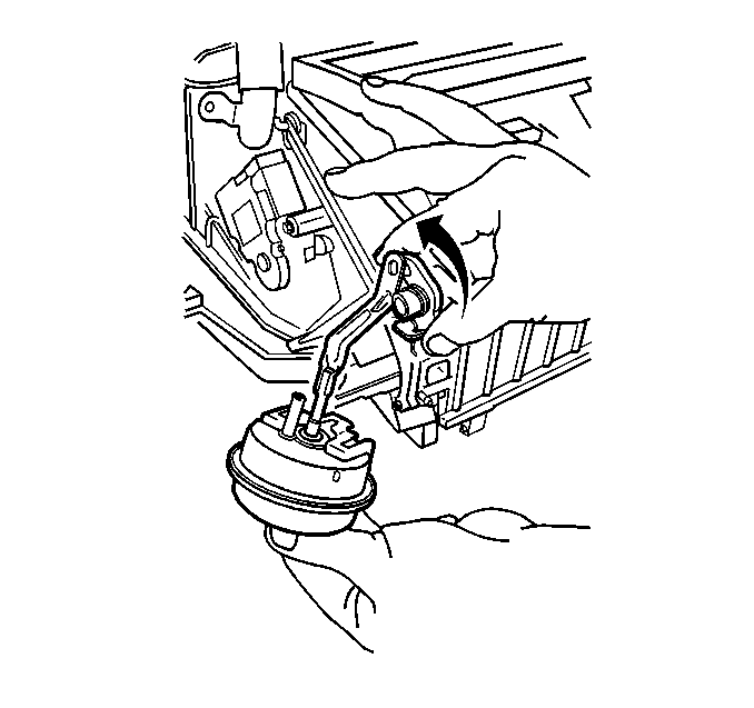
- Remove the mode actuator off the slides of the HVAC module assembly.
- Disconnect the actuator pushrod from the mode door lever and remove the actuator.


Installation Procedure
- Connect the actuator pushrod to the mode door lever.
- Position the actuator on to the slides of the HVAC module assembly.
- Ensure that the lock tab (1) locks the actuator.
- Connect the vacuum lines to the mode actuator.
- Connect support clip for the ignition switch harness.
- Install the IP knee bolster bracket. Refer to Driver Knee Bolster Bracket Replacement in Instrument Panel, Gages, and Console.
- Install the left instrument panel (IP) insulator. Refer to Instrument Panel Insulator Panel Replacement - Left Side in Instrument Panel, Gages, and Console.


