Instrument Panel Electrical Center or Junction Block Replacement - Left Side for Chevrolet Impala 2003
Removal Procedure
- Disconnect the negative battery cable. Refer to Battery Negative Cable Disconnection and Connection in Engine Electrical.
- Remove the left I/P fuse block access hole cover.
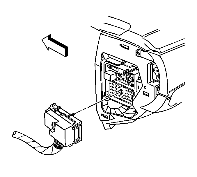
- Disconnect the outboard wiring harness connector C2 from the junction block.
- Remove the connector position assurance (CPA) from the yellow inflatable restraint connector. Disconnect and reposition the yellow inflatable restraint connector for access to the bolts.
- Remove the steering column filler. Refer to Steering Column Opening Filler Replacement in Instrument Panel, Gages, and Console.
- Remove the I/P driver knee bolster. Refer to Driver Knee Bolster Bracket Replacement in Instrument Panel, Gages, and Console.
- Disconnect the inner wiring harness connector from the junction block.
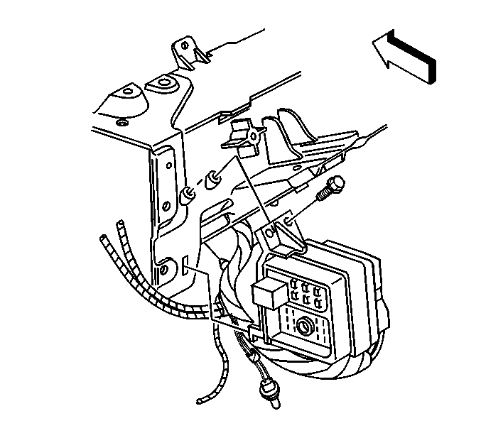
- Remove the junction block bolts.
- Remove the junction block tab from the slot in the cross vehicle beam. Pull the junction block away from the I/P.
- Remove the junction block.
Installation Procedure
- Install the junction block tab to the slot in the cross vehicle beam.
- Install the junction block bolts.
- Connect the inner wiring harness connector to the junction block.
- Install the I/P driver knee bolster. Refer to Driver Knee Bolster Bracket Replacement in Instrument Panel, Gages, and Console.
- Install the steering column filler. Refer to Steering Column Opening Filler Replacement in Instrument Panel, Gages, and Console.
- Connect the yellow inflatable restraint connector. Install the CPA. Attach the connector to the junction block.
- Connect the outboard wiring harness connector C2 to the junction block.
- Install the left I/P fuse block access hole cover.
- Connect the negative battery cable. Refer to Battery Negative Cable Disconnection and Connection in Engine Electrical.
Notice: Use the correct fastener in the correct location. Replacement fasteners must be the correct part number for that application. Fasteners requiring replacement or fasteners requiring the use of thread locking compound or sealant are identified in the service procedure. Do not use paints, lubricants, or corrosion inhibitors on fasteners or fastener joint surfaces unless specified. These coatings affect fastener torque and joint clamping force and may damage the fastener. Use the correct tightening sequence and specifications when installing fasteners in order to avoid damage to parts and systems.
Tighten
Tighten the junction block bolts to 10 N·m (89 lb in).
Tighten
Tighten the inner wiring harness connector bolt to 7 N·m (62 lb in).
Tighten
Tighten the body wiring harness connector bolt to 7 N·m (62 lb in).
