Removal Procedure
- Disconnect the negative battery cable. Refer to Battery Negative Cable Disconnection and Connection in Engine Electrical.
- Remove the rear suspension support bolt.
- Remove the rear compartment trim panel. Refer to Rear Compartment Trim Panel Replacement in Body Rear End.
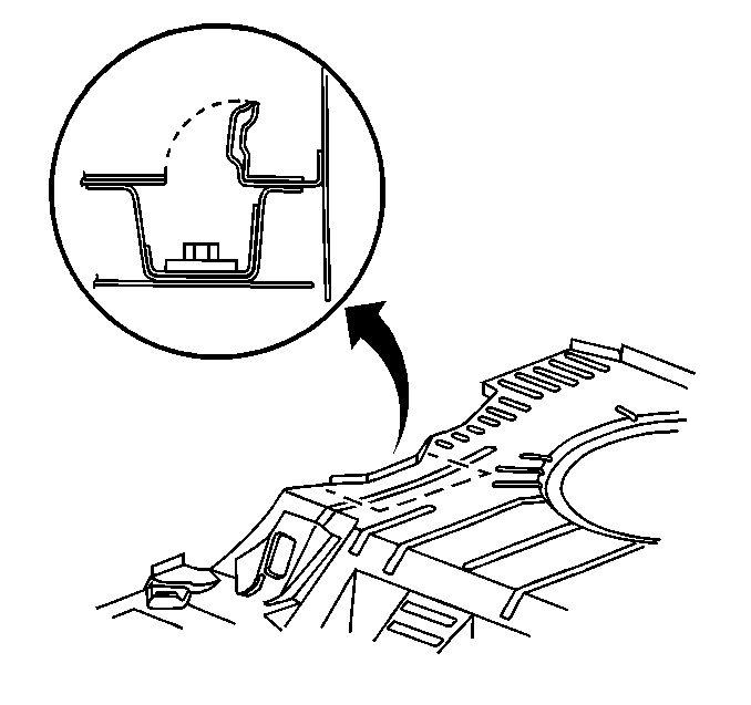
- Place a center punch through the damaged rear suspension support nut. Strike the center punch using a hammer. The punch will leave a dimple on the floor. Use the dimple in order to locate the area where the frame crossmember nut will be removed.
- Use a cutoff wheel in order to cut an access panel.
- Lift the access panel upward in order to gain access to the frame crossmember nut retainer.
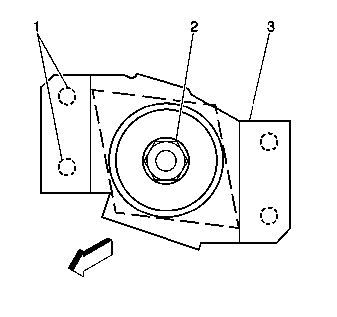
- Use an air chisel in order to break away the spot welds (1) on one side of the frame crossmember nut retainer (3).
- Lift 1 side of the frame crossmember nut retainer enough in order to remove the frame crossmember nut.
- Remove the rear suspension support nut (2).
Important: Do not cut or damage the adjacent panels or the reinforcements.

Important: Reuse the frame crossmember nut retainer if the retainer is not damaged from the stripped out bolt.

Installation Procedure
- Install the rear suspension support nut (2).
- Lower the frame crossmember nut retainer (3) into place. Ensure that the following conditions exist:
- Spot weld the frame crossmember nut retainer in the original location.
- Apply corrosion protection. Refer to Anti-Corrosion Treatment and Repair in General Information.
- Install the new rear suspension support bolt to the frame crossmember nut.
- Reposition the panel downward to the original position.
- Stitch weld the panel back to the original position using 25 mm (0.98 in) welds along the seam. Leave 25 mm (0.98 in) gaps between the welds. A solid joint with minimal heat distortion will result. Continue to finish the stitch weld procedure.
- Use a small grinder in order to remove the excess material from the floor panel until the following conditions exist:
- Apply corrosion protection. Refer to Anti-Corrosion Treatment and Repair in Paint/Coatings.
- Install the rear compartment trim panel. Refer to Rear Compartment Trim Panel Replacement in Body Rear End.
- Apply anti-corrosion compound GM P/N 12346225 or equivalent. Thoroughly coat both sides of the repair area through the access hole.
- Connect the negative battery cable. Refer to Battery Negative Cable Disconnection and Connection in Engine Electrical.

| • | The frame crossmember nut is correctly positioned. |
| • | The frame crossmember nut operates correctly. |
Notice: Use the correct fastener in the correct location. Replacement fasteners must be the correct part number for that application. Fasteners requiring replacement or fasteners requiring the use of thread locking compound or sealant are identified in the service procedure. Do not use paints, lubricants, or corrosion inhibitors on fasteners or fastener joint surfaces unless specified. These coatings affect fastener torque and joint clamping force and may damage the fastener. Use the correct tightening sequence and specifications when installing fasteners in order to avoid damage to parts and systems.
Tighten
Tighten the rear suspension support bolt to 105 N·m (77 lb ft).

| • | The floor panel is smooth. |
| • | The floor panel is free from rough edges. |
