GM Service Manual Online
For 1990-2009 cars only
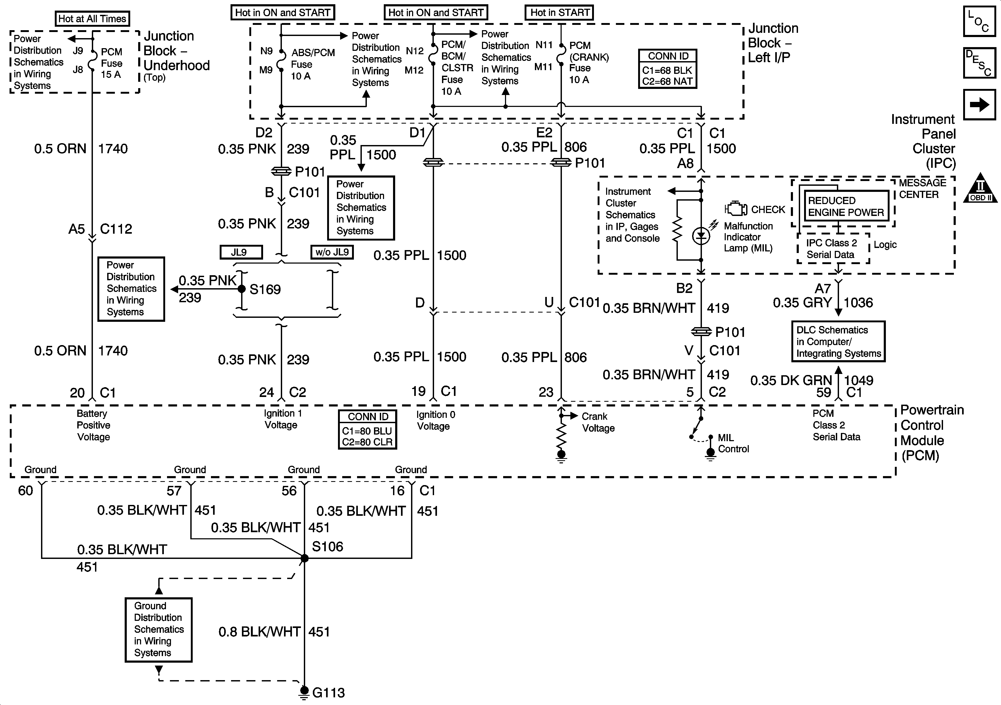
Figure 1:

DLC, Grounds, MIL, and Power


Object Number: 1551468  Size: FS
Master Electrical Component List
Powertrain Control Module Description
5 Volt and Low Reference Bussing
OBD II Symbol Description Notice
Junction Block - Underhood (Top) Bussing
ABS/PCM, SRS, STOP, and TURN SIGNAL Fuses
A/C/CRUISE, CRUISE, PCM/BCM/CLSTR, and PCM (CRANK) Fuses
ABS/PCM, SRS, STOP, and TURN SIGNAL Fuses
A/C/CRUISE, CRUISE, PCM/BCM/CLSTR, and PCM (CRANK) Fuses
Gages, Illumination, and Indicators
DLC
G113 - 2 of 2
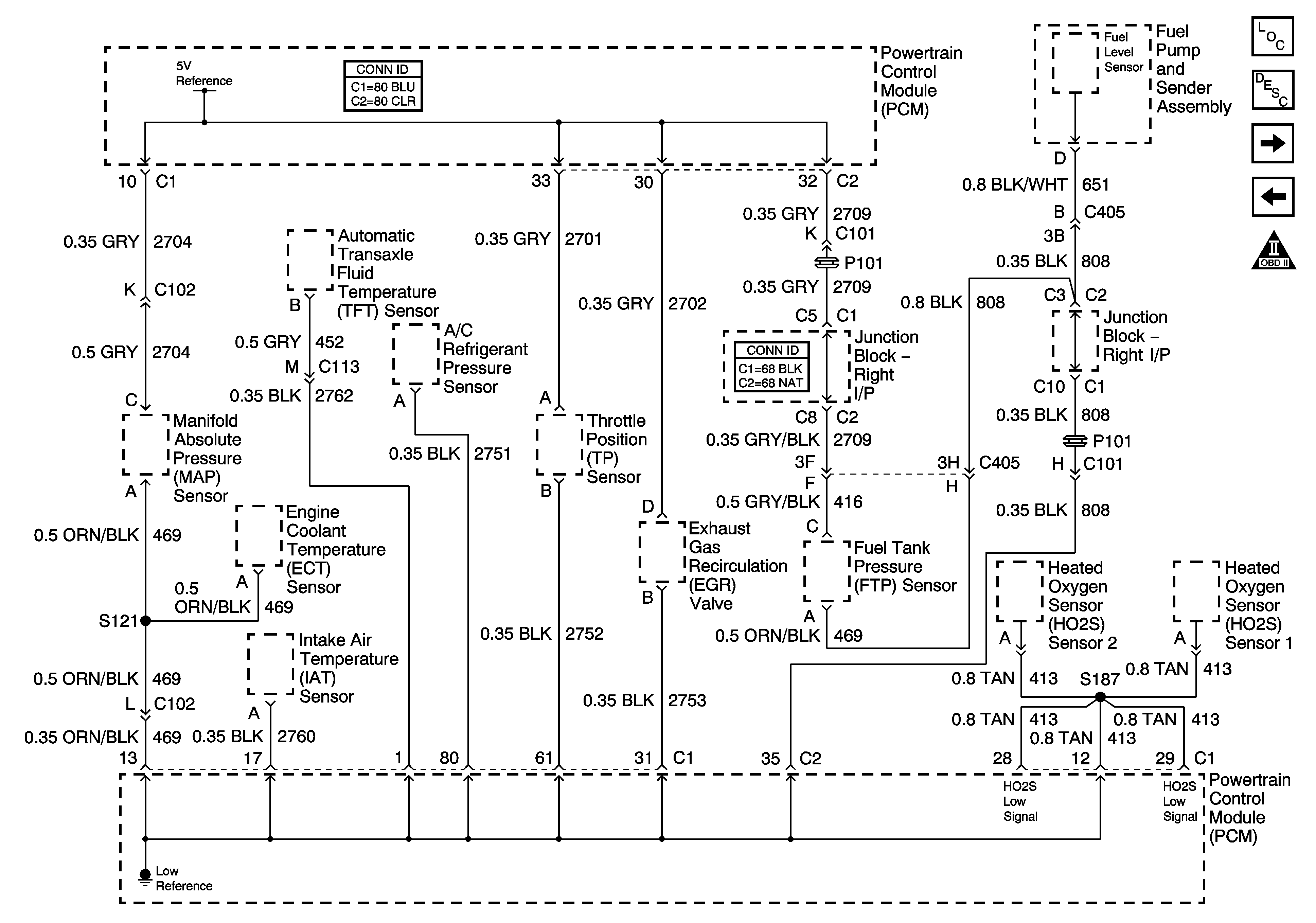
Figure 2:

5-volt and Low Reference Bussing


Object Number: 1766528  Size: FS
Master Electrical Component List
Powertrain Control Module Description
ECT, IAT, MAP, and TP Sensors
DLC, Grounds, Mil, and Power
OBD II Symbol Description Notice
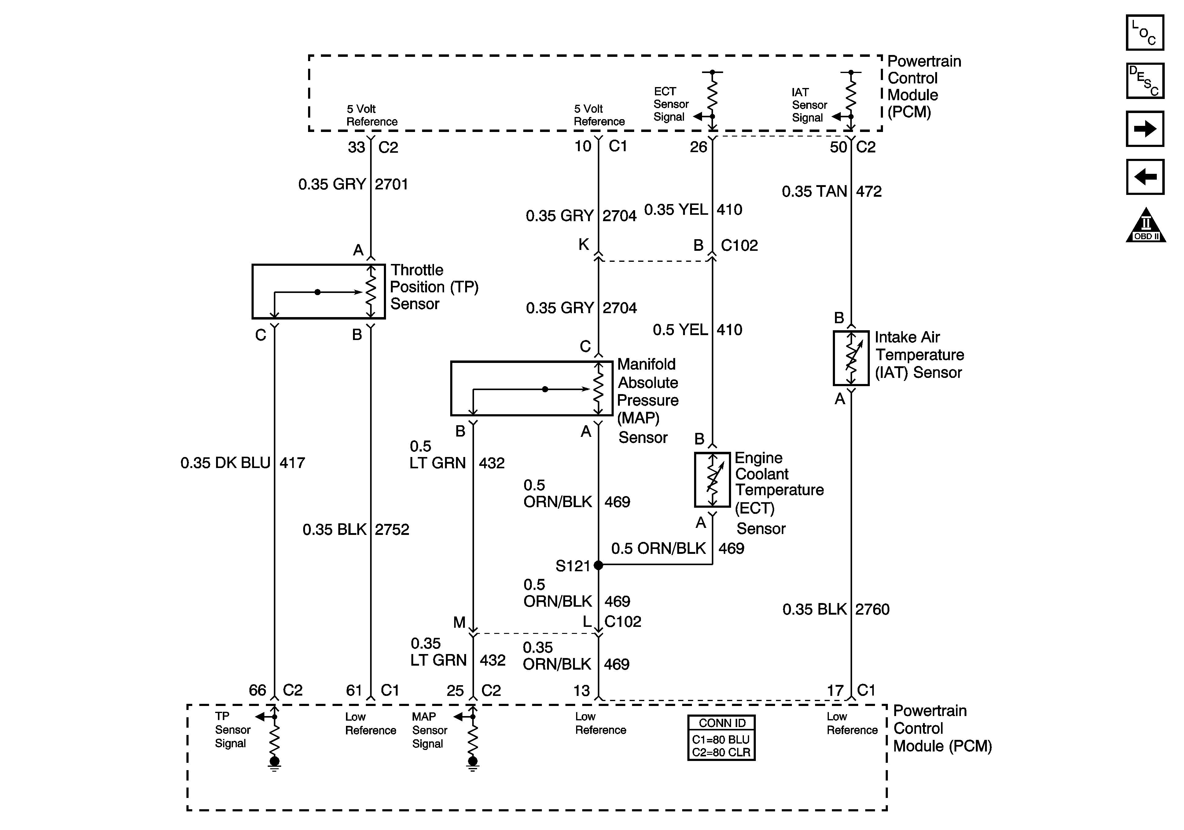
Figure 3:

ECT, IAT, MAP, and TP Sensors


Object Number: 1284571  Size: FS
Master Electrical Component List
Powertrain Control Module Description
MAF, and VSS
5 Volt and Low Reference Bussing
OBD II Symbol Description Notice
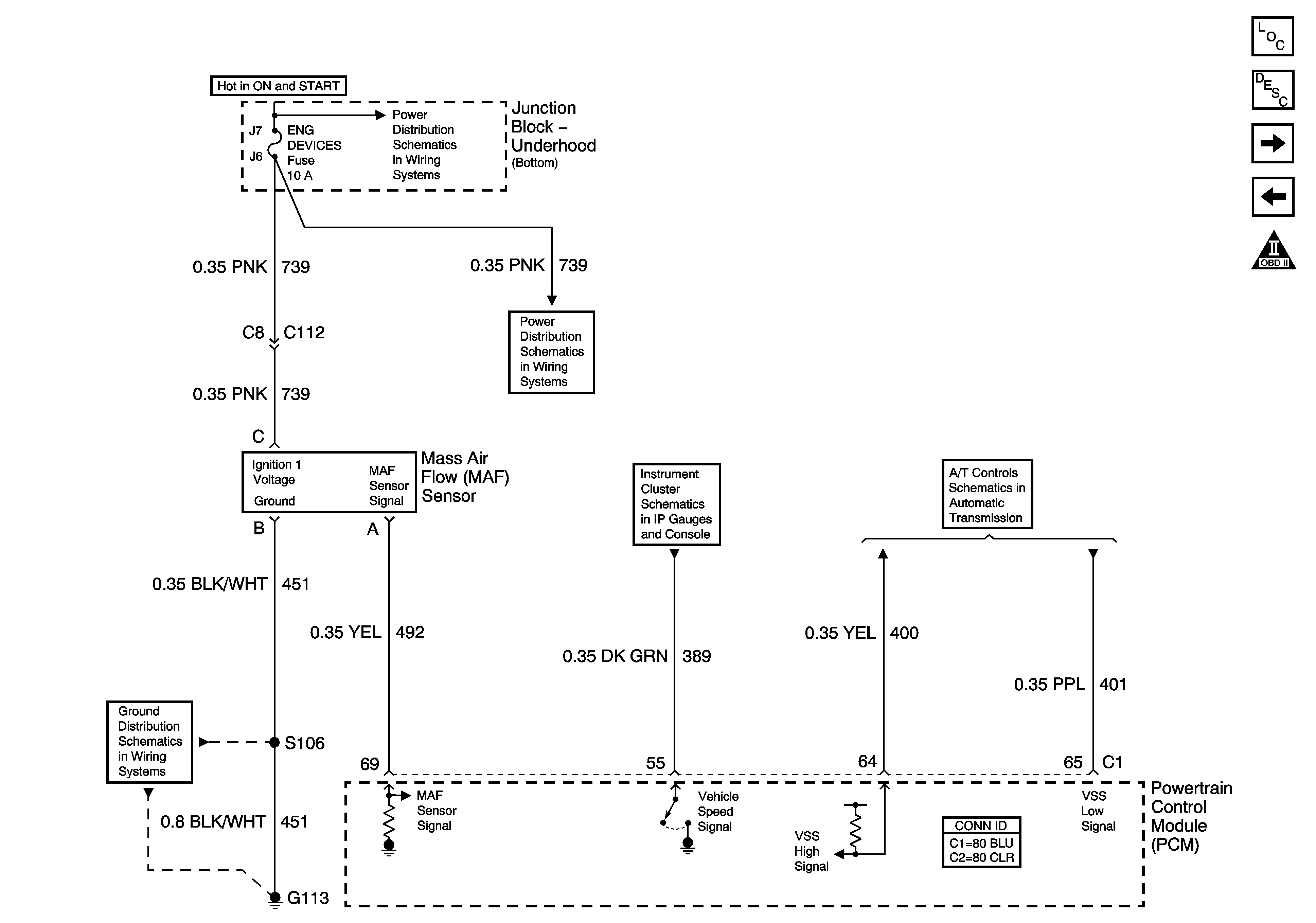
Figure 4:

MAF and VSS


Object Number: 885056  Size: FS
Master Electrical Component List
Powertrain Control Module Description
HO2S
ECT, IAT, MAP, and TP Sensors
OBD II Symbol Description Notice
Junction Block - Underhood (Bottom) Bussing
DFI MDL, ENG DEVICES, and OXY SEN Fuses
DLC, Ground, Odometer/PRNDL, and VSS
ISS, Pressure Control Solenoid Valve, and VSS
G113 - 2 of 2
Figure 5:

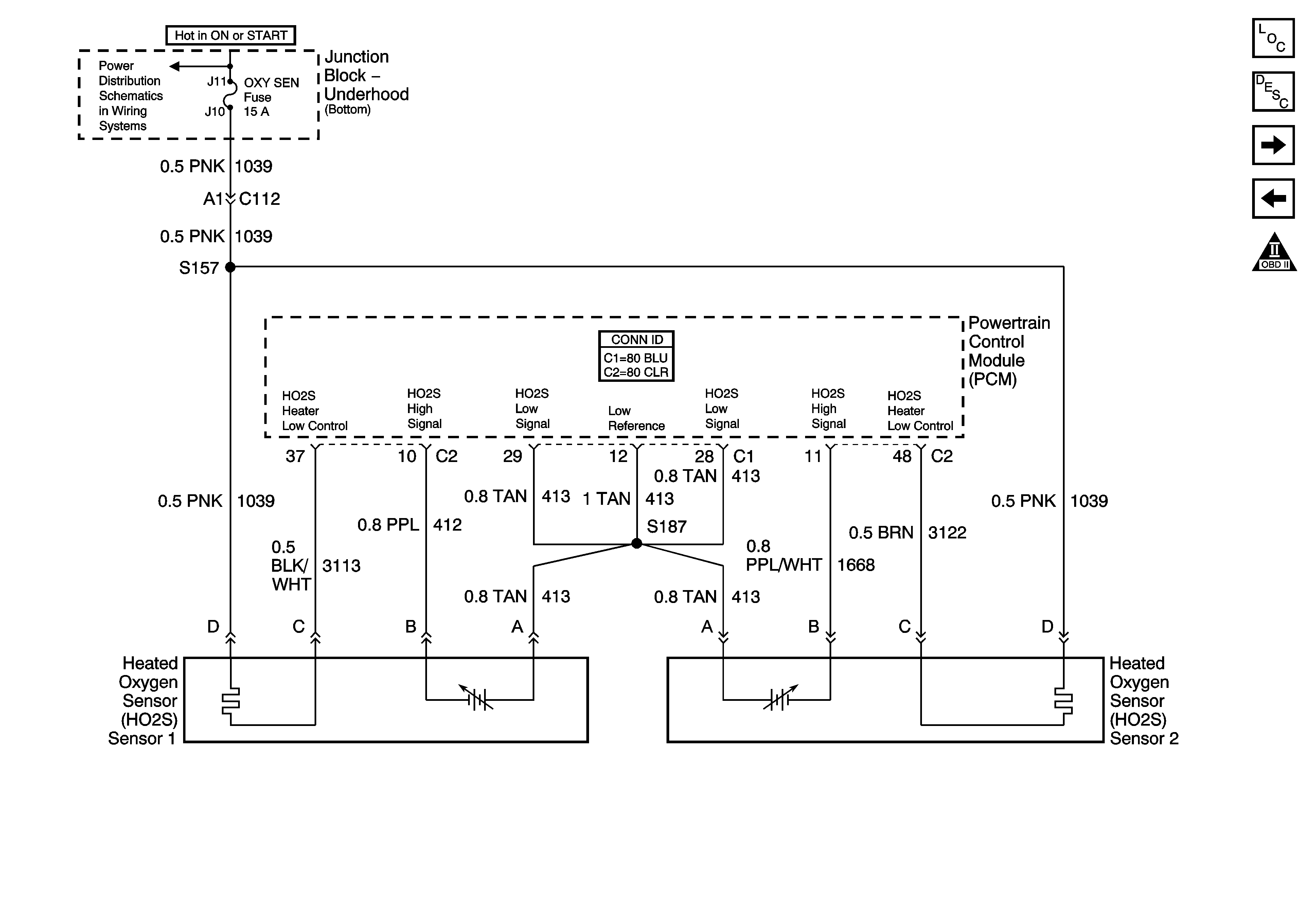
HO2S


Object Number: 1766534  Size: FS
Master Electrical Component List
Powertrain Control Module Description
Ignition Controls
MAF, and VSS
OBD II Symbol Description Notice
Junction Block - Underhood (Bottom) Bussing
Figure 6:

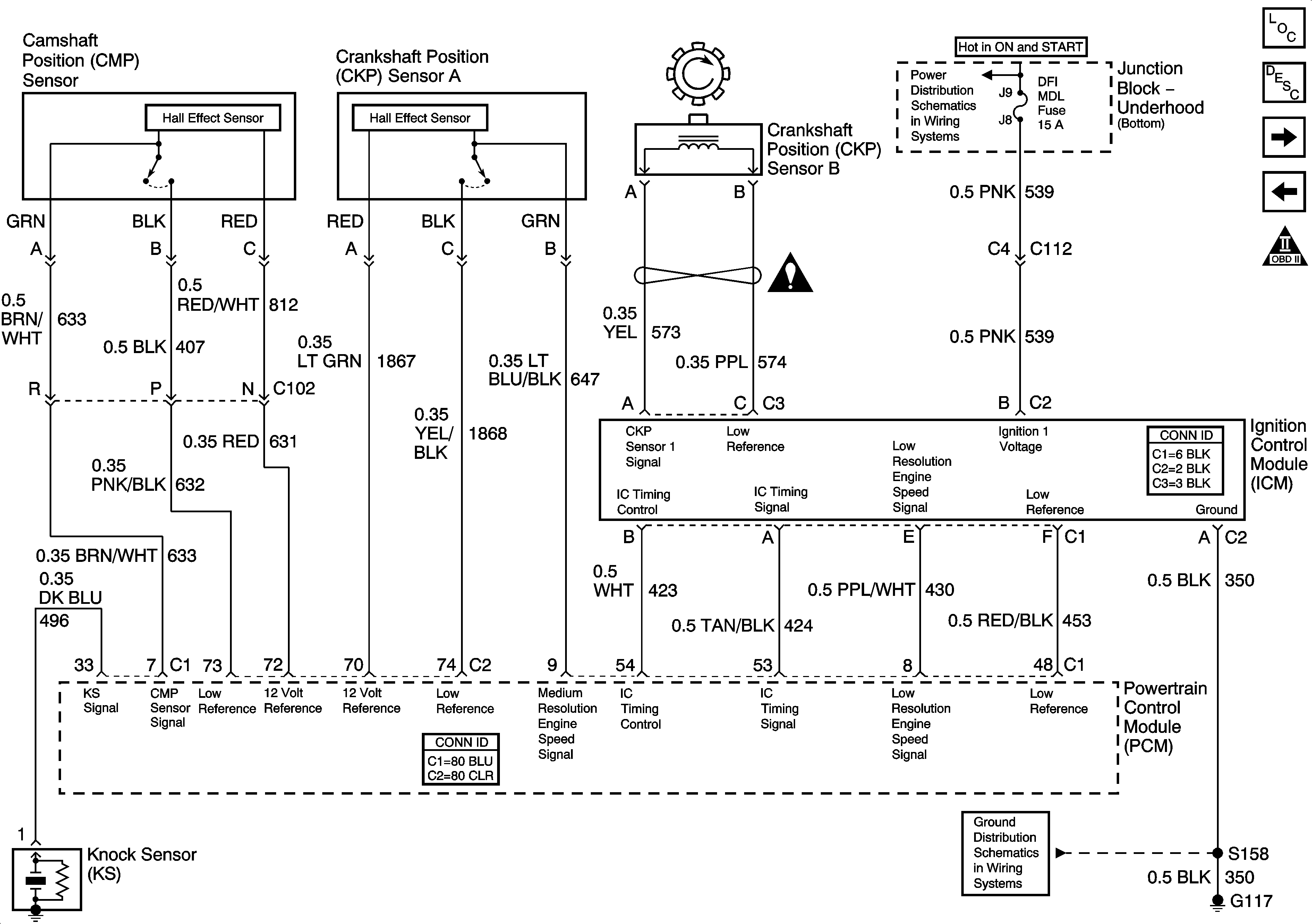
Ignition Controls


Object Number: 651831  Size: FS
Master Electrical Component List
Electronic Ignition (EI) System Description
Fuel Pump
HO2S
OBD II Symbol Description Notice
Junction Block - Underhood (Bottom) Bussing
Engine Controls Schematic Icons
G100, G111, G113 - 1 of 2, G117, G151, G171
Figure 7:

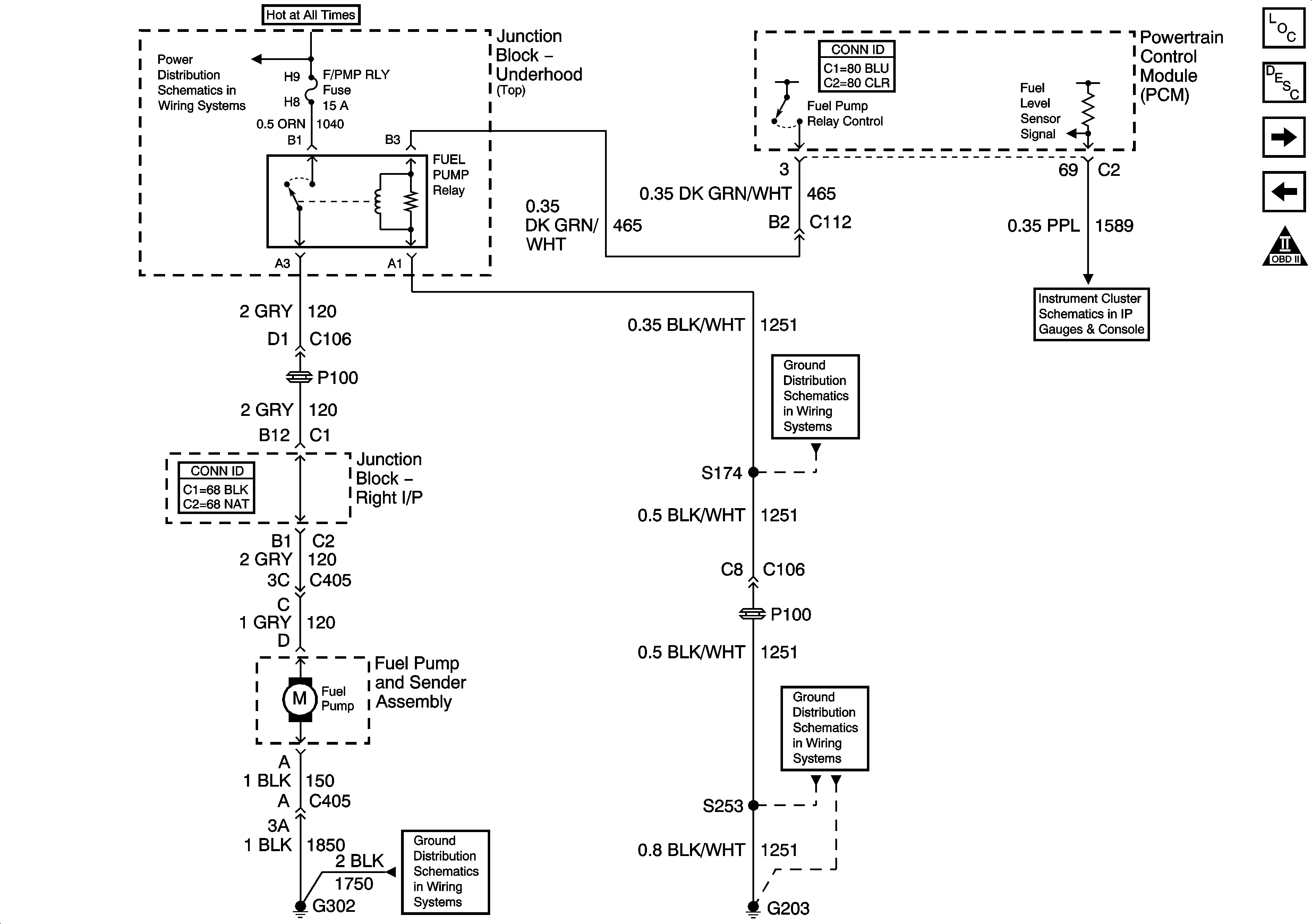
Fuel Pump


Object Number: 1346861  Size: FS
Master Electrical Component List
Fuel System Description
Fuel Injectors
Ignition Controls
OBD II Symbol Description Notice
Junction Block - Underhood (Top) Bussing
Gages, Illumination, and Indicators
G203 - 3 of 3
G203 - 1 of 3
G302 - 1 of 2
Figure 8:

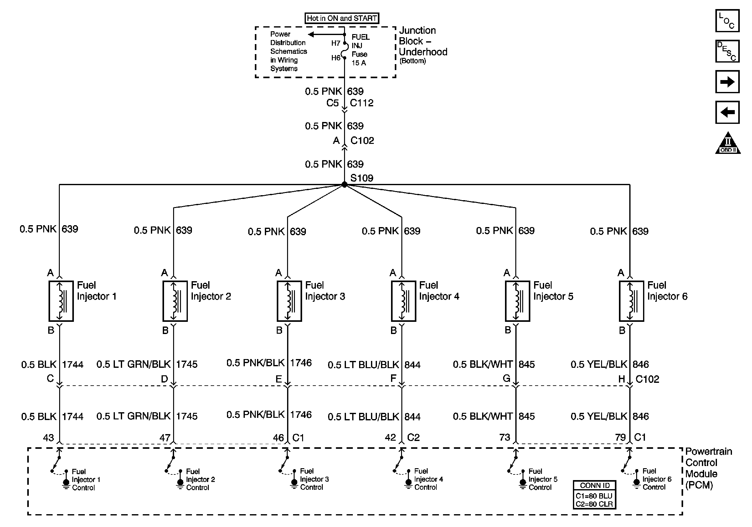
Fuel Injectors


Object Number: 798540  Size: FS
Master Electrical Component List
Fuel System Description
EVAP and FTP
Fuel Pump
OBD II Symbol Description Notice
Junction Block - Underhood (Bottom) Bussing
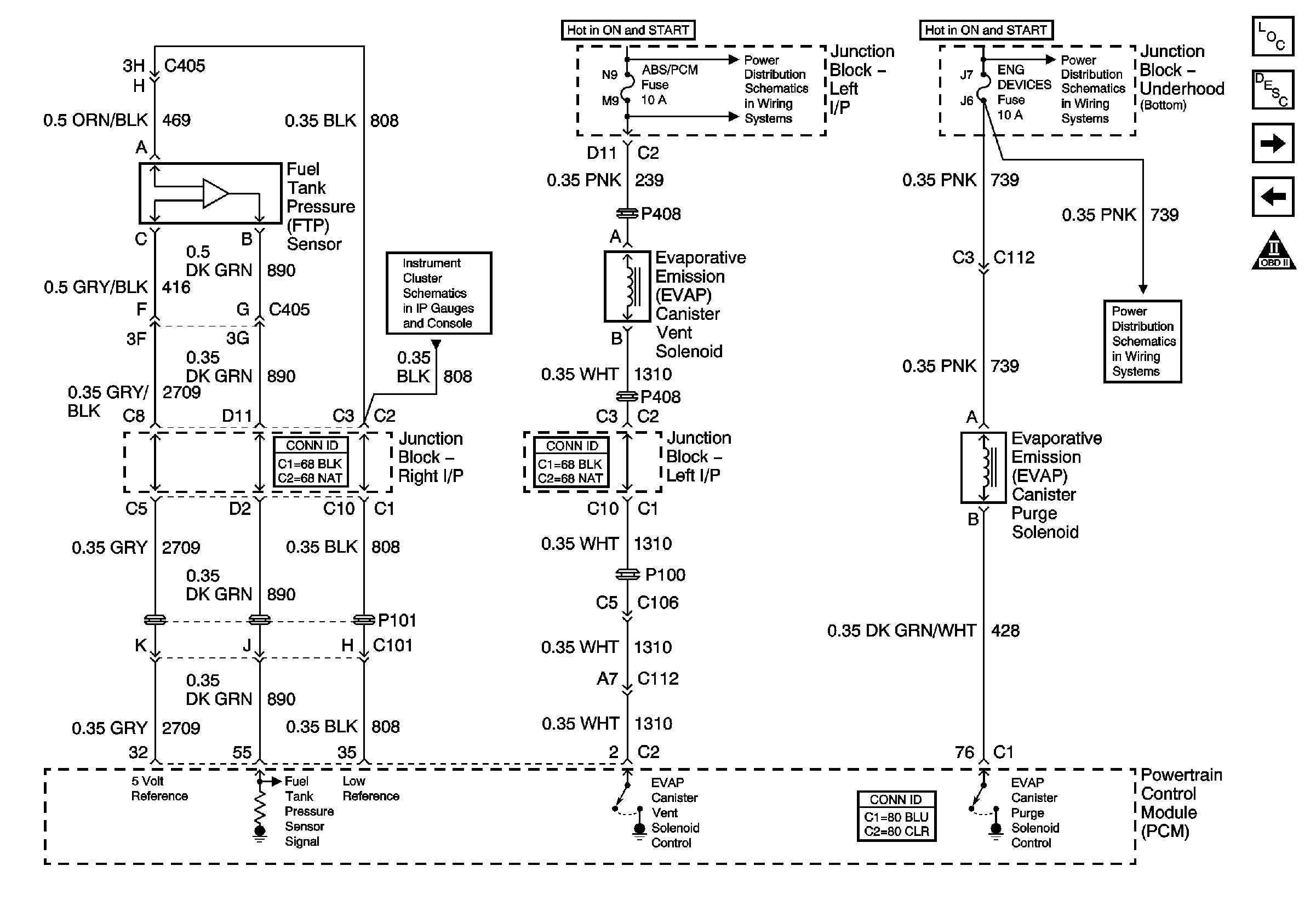
Figure 9:

EVAP and FTP


Object Number: 784628  Size: FS
Master Electrical Component List
Evaporative Emission Control System Description
EGR and IAC
Fuel Injectors
OBD II Symbol Description Notice
ABS/PCM, SRS, STOP, and TURN SIGNAL Fuses
Junction Block - Underhood (Bottom) Bussing
Gages, Illumination, and Indicators
DFI MDL, ENG DEVICES, and OXY SEN Fuses
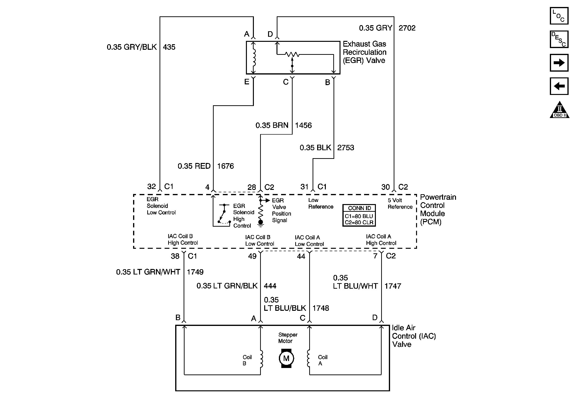
Figure 10:

EGR and IAC


Object Number: 885062  Size: FS
Master Electrical Component List
Exhaust Gas Recirculation (EGR) System Description
Subsystem References
EVAP and FTP
OBD II Symbol Description Notice
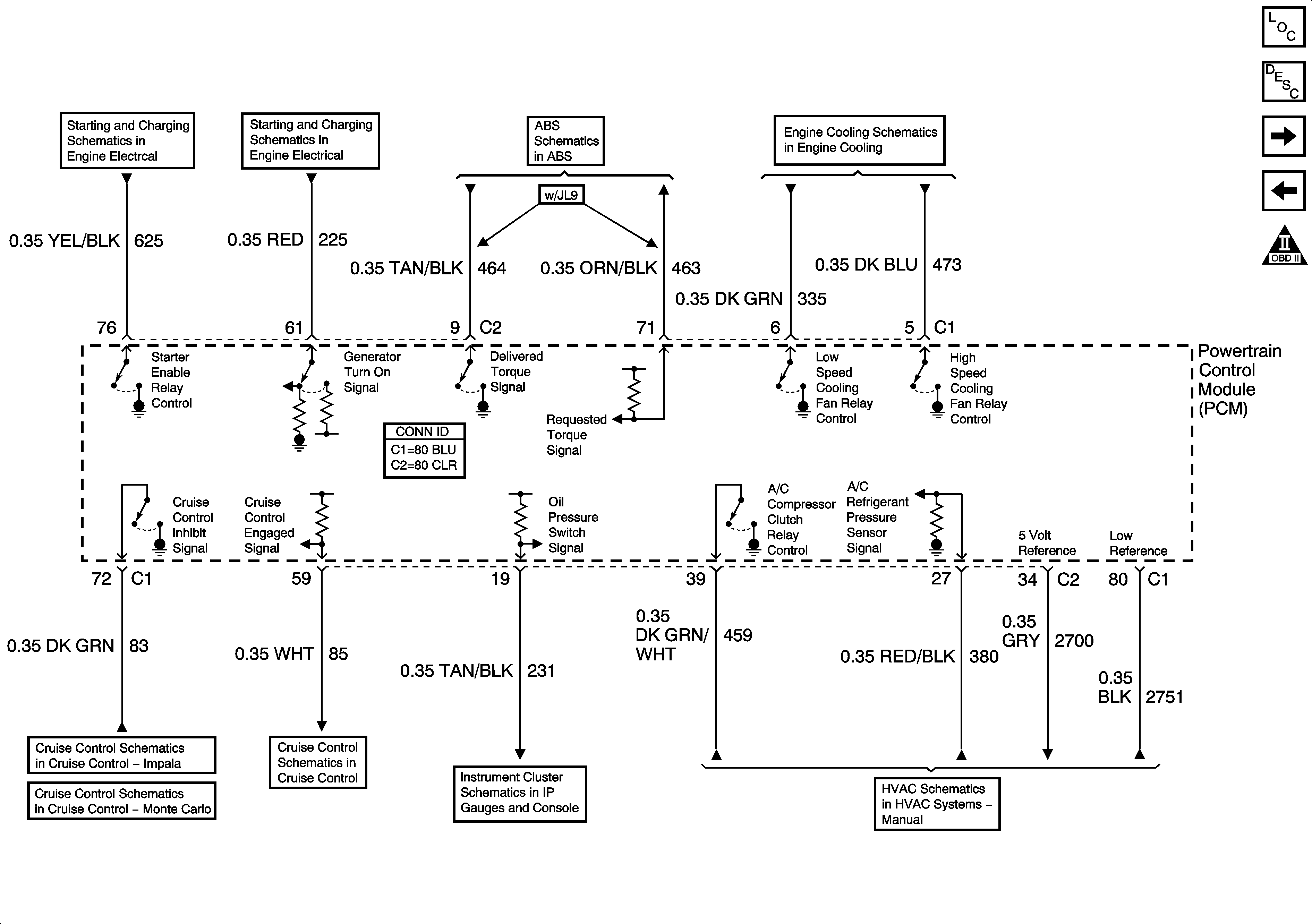
Figure 11:

Subsystem References


Object Number: 1552604  Size: FS
Master Electrical Component List
Powertrain Control Module Description
A/T References
EGR and IAC
OBD II Symbol Description Notice
Engine Cranking
Charge Control and Indicator
Stop Lamps and Torque Signals
Engine Cooling
Monte Carlo
Impala
Indicator Control
Message Center
A/C Compressor Controls
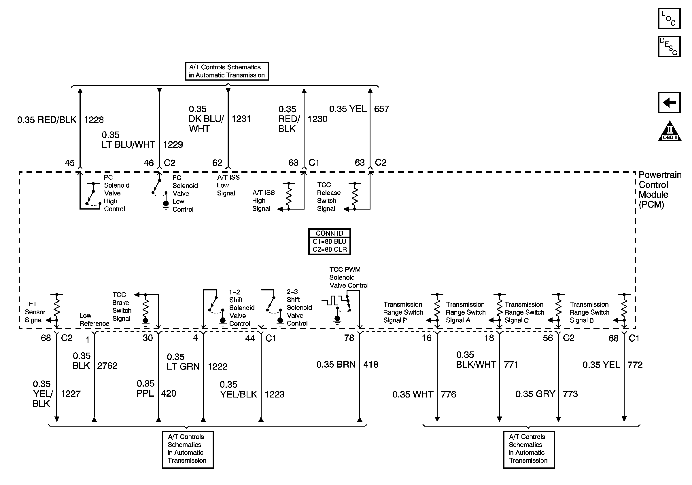
Figure 12:

A/T References


Object Number: 885065  Size: FS
Master Electrical Component List
Powertrain Control Module Description
Subsystem References
OBD II Symbol Description Notice
ISS, Pressure Control Solenoid Valve, and VSS
Soleniods, TCC, and TFT
Internal Mode Switch (IMS)