Coolant Recovery Reservoir Replacement LS4
Removal Procedure
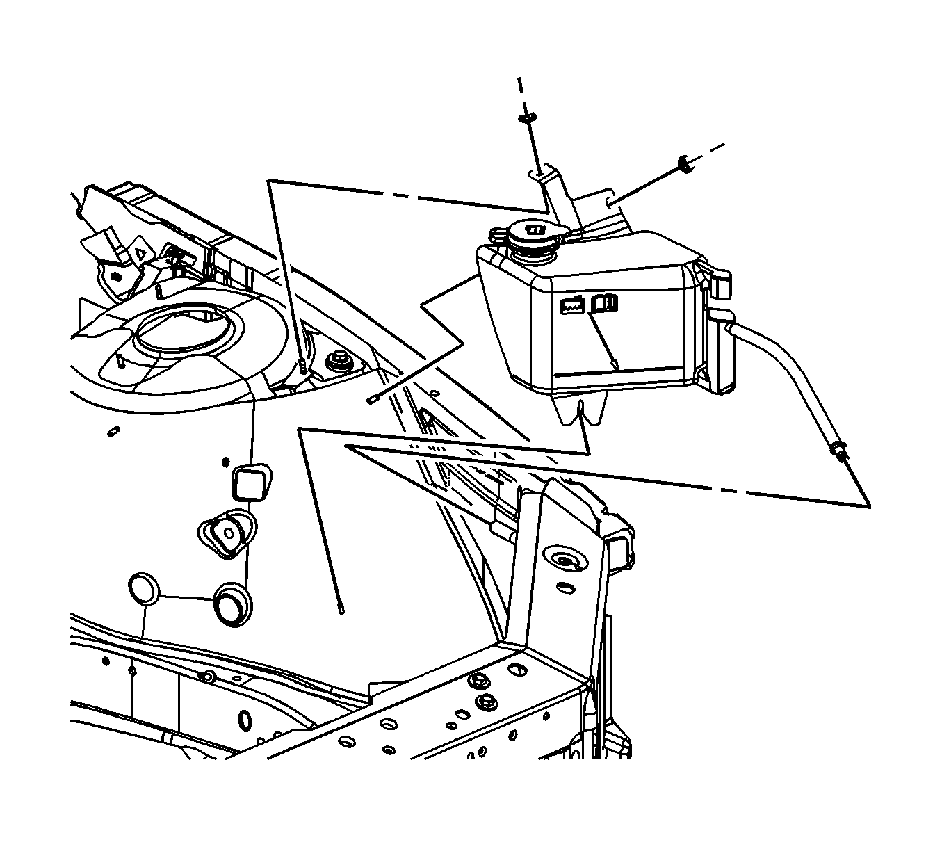
- Remove the front fender upper diagonal brace. Refer to Front Fender Upper Diagonal Brace Replacement .
- Reposition the coolant recovery reservoir hose clamp aside at the radiator overflow fitting.
- Disconnect the coolant recovery reservoir hose from the radiator overflow hose.
- Remove the coolant recovery reservoir nuts from the shock tower studs.
- Remove the coolant recovery reservoir from the lower retainer and the shock tower studs.
- Drain the coolant from the coolant recovery reservoir into a clean container.

Installation Procedure
- Install the coolant recovery reservoir to the lower retainer and the shock tower studs.
- Install the nuts to the shock tower studs.
- Lubricate the reservoir hose with clean water. Install the coolant reservoir hose to the radiator overflow hose.
- Position the coolant reservoir hose clamp to the radiator overflow hose fitting.
- Install the front fender upper diagonal brace. Refer to Front Fender Upper Diagonal Brace Replacement .
- Fill the coolant recovery reservoir to the proper level. Refer to Cooling System Draining and Filling .

Notice: Refer to Fastener Notice in the Preface section.
Tighten
Tighten the nuts to 3.3 N·m (29 lb in).
Coolant Recovery Reservoir Replacement LZE, LZ4, LZG
Removal Procedure
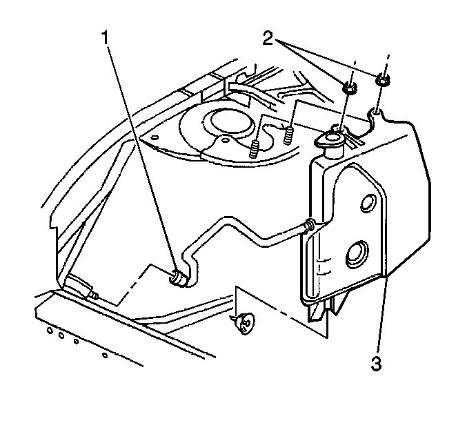
- Reposition the reservoir hose clamp (1).
- Remove the reservoir hose from the radiator overflow neck.
- Remove the coolant recovery reservoir nuts (2) from the shock tower studs.
- Remove the coolant recovery reservoir (3) from the lower retainer and the shock tower studs .
- Drain the coolant from the recovery reservoir in to a clean container.

Installation Procedure
- Install the coolant recovery reservoir (3) onto the lower retainer and the shock tower studs.
- Install the coolant recovery reservoir nuts (2) to the shock tower studs.
- Lubricate the reservoir hose with clean water. Route the hose to the radiator overflow neck fitting.
- Install the coolant reservoir hose (1) to the overflow neck fitting.
- Install the reservoir hose and clamp (1), with the clamp tabs at the 11 o'clock position, to the radiator overflow fitting on the radiator filler neck. The hose end must be flush against the radiator filler neck. Seat the clamp squarely between the radiator filler neck and the flared end of the fitting.
- Fill the coolant recovery reservoir to the proper level.

Notice: Use the correct fastener in the correct location. Replacement fasteners must be the correct part number for that application. Fasteners requiring replacement or fasteners requiring the use of thread locking compound or sealant are identified in the service procedure. Do not use paints, lubricants, or corrosion inhibitors on fasteners or fastener joint surfaces unless specified. These coatings affect fastener torque and joint clamping force and may damage the fastener. Use the correct tightening sequence and specifications when installing fasteners in order to avoid damage to parts and systems.
Tighten
Tighten the nuts to 3.3 N·m (29 lb in).
