Floor Panel Replacement Impala
Removal Procedure
Caution: Refer to Approved Equipment for Collision Repair Caution in the Preface section.

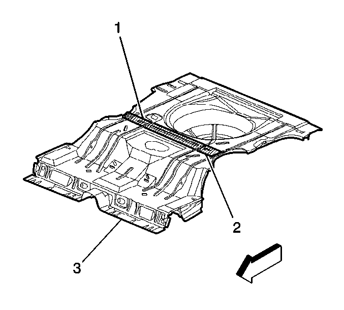
Important: The damaged rear floor should be cut along the rearward edge of the rear crossbar (1), and the service part should be cut so that the new floor section extends to the forward edge of the rear crossbar (2).
This allows the two sections to overlap where the crossbar is attached (2). The cut to the damaged floor will be about 790 mm (31 1/8 in) from the rear edge of the floor panel.
- Remove all related panels and components as necessary, including the following:
| • | The quarter panel extensions |
- Visually inspect and restore as much of the damage as possible.
- Remove the following as necessary:
| • | The anti-corrosion materials |
- Locate and mark all factory welds rearward of the rear crossbar including those along the lower edge of the wheelhouse.
- Note the number and location of welds for installation of the floor service assembly.
- Drill out all factory welds.
Important: Drill out the factory welds rearward of the crossbar only. Do not drill out the welds attaching the floor to the crossbar.
- Cut the damaged floor along the rear edge of the crossbar.
- Do not damage the following:
- Remove the damaged floor section.
Installation Procedure

Important: The service part is supplied as a rear floor assembly.
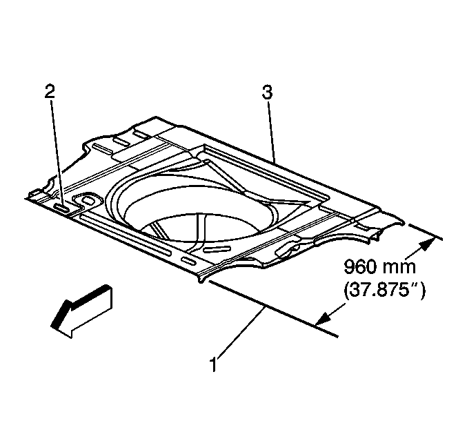
- Measure 960 mm (37 ¾ in) forward from the rear edge of the rear floor service assembly, mark the location, and cut accordingly.
- Prepare the mating surfaces as necessary.
- Check for proper fit.
- Allow the floor service assembly (3) to overlap the original floor on top of the rear crossbar (2).
- Mark the location of the rear rail and crossbar flanges on the bottom of the floor service assembly.
- Drill 8 mm (5/16 in) plug weld holes as necessary in the locations noted from the original floor assembly (3).
- Drill holes approximately 40 mm (1 in) apart where the new floor section attaches to the rear rail and crossbar flanges.
- Position the service assembly and check for proper fit.
- Apply 3M Weld-Thru Coating P/N 05916 or equivalent to all mating surfaces.
- Plug weld accordingly (1).
- Clean and prepare all welded surfaces.
Important: Prior to refinishing, refer to GM 4901MD-99 Refinish Manual for recommended products. Do not combine paint systems. Refer to paint manufacturer's recommendations.
- Apply 2-part catalyzed primer.
Important: The rear crossbar areas must be properly sealed from moisture and dirt to seal both the front and rear edges of the crossbar as well as the inner seams.
- Apply the following materials as necessary:
| • | The anti-corrosion materials |
- Install all related panels and components.


