For 1990-2009 cars only
Power Vacuum Brake Booster Replacement 5.3L
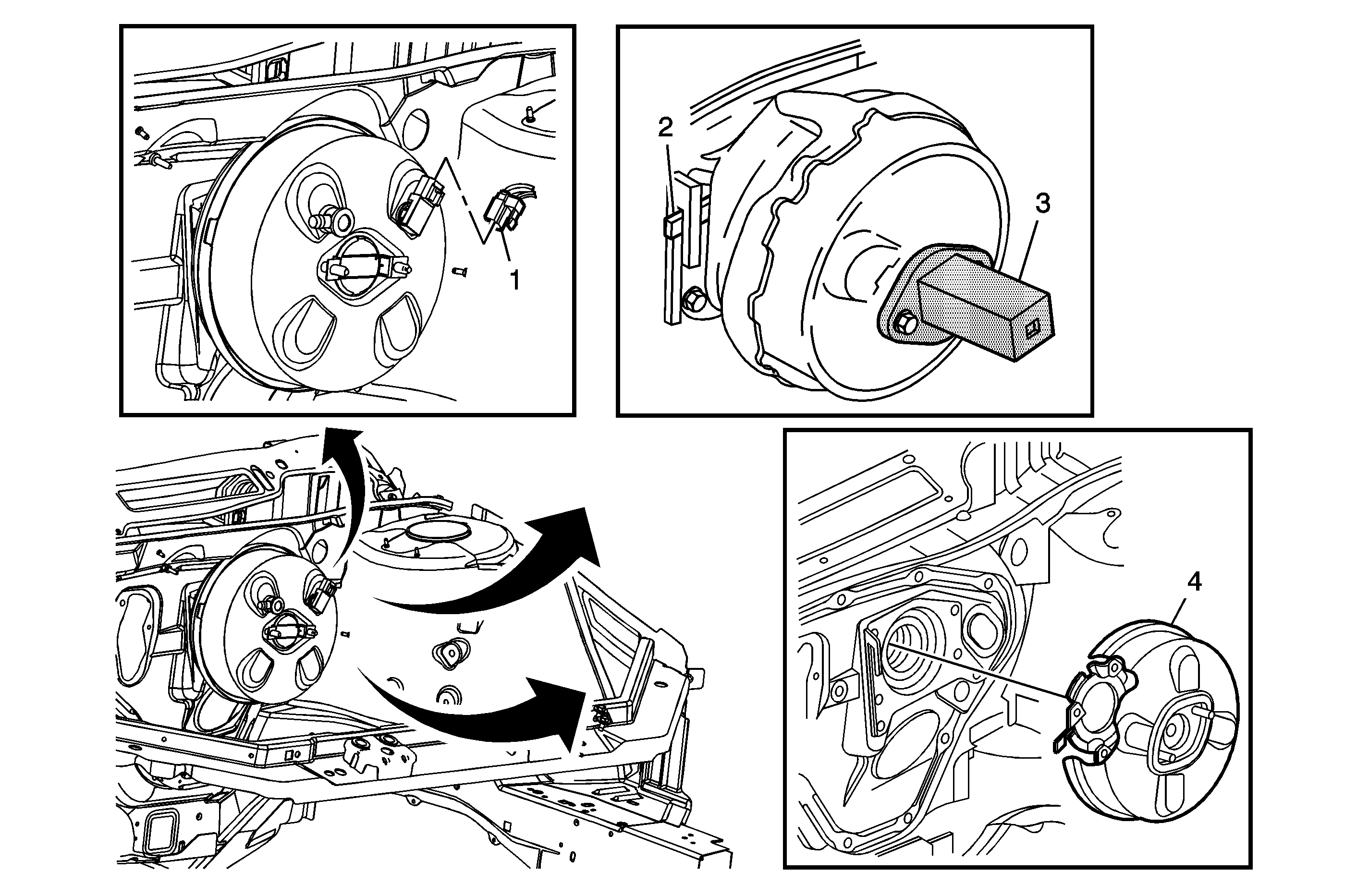
Callout | Component Name | ||||
|---|---|---|---|---|---|
Preliminary Procedures
| |||||
1 | Brake Booster Electrical Connector | ||||
2 | Release Lever | ||||
3 | Tool Tip Special ToolsJ 22805-B Brake Booster Holder | ||||
4 | Brake Booster Tip
| ||||
Power Vacuum Brake Booster Replacement 3.5L, 3.9L
Special Tools
J-22805-B Brake Booster Holder
Removal Procedure
- Remove the intake manifold cover. Refer to Intake Manifold Cover Replacement for the 3.5L engine or Intake Manifold Cover Replacement for the 3.9L engine.
- Remove the air cleaner outlet duct. Refer to Air Cleaner Outlet Duct Replacement for the 3.5L engine or Air Cleaner Outlet Duct Replacement for the 3.9L engine.
- Without draining the engine coolant or disconnecting the heater hoses, remove the heater pipe assembly from the throttle body and position aside. Refer to Heater Pipes Replacement.
- Disconnect the brake fluid level switch electrical connector.
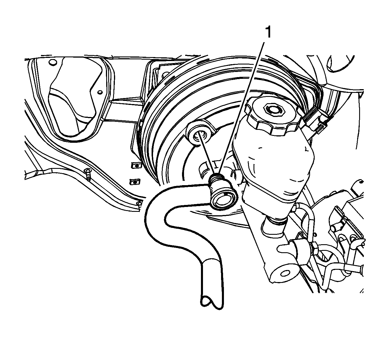
- Disconnect the vacuum power brake booster check valve and hose assembly (1).
- Disconnect the vacuum power brake booster vacuum sensor electrical connector.
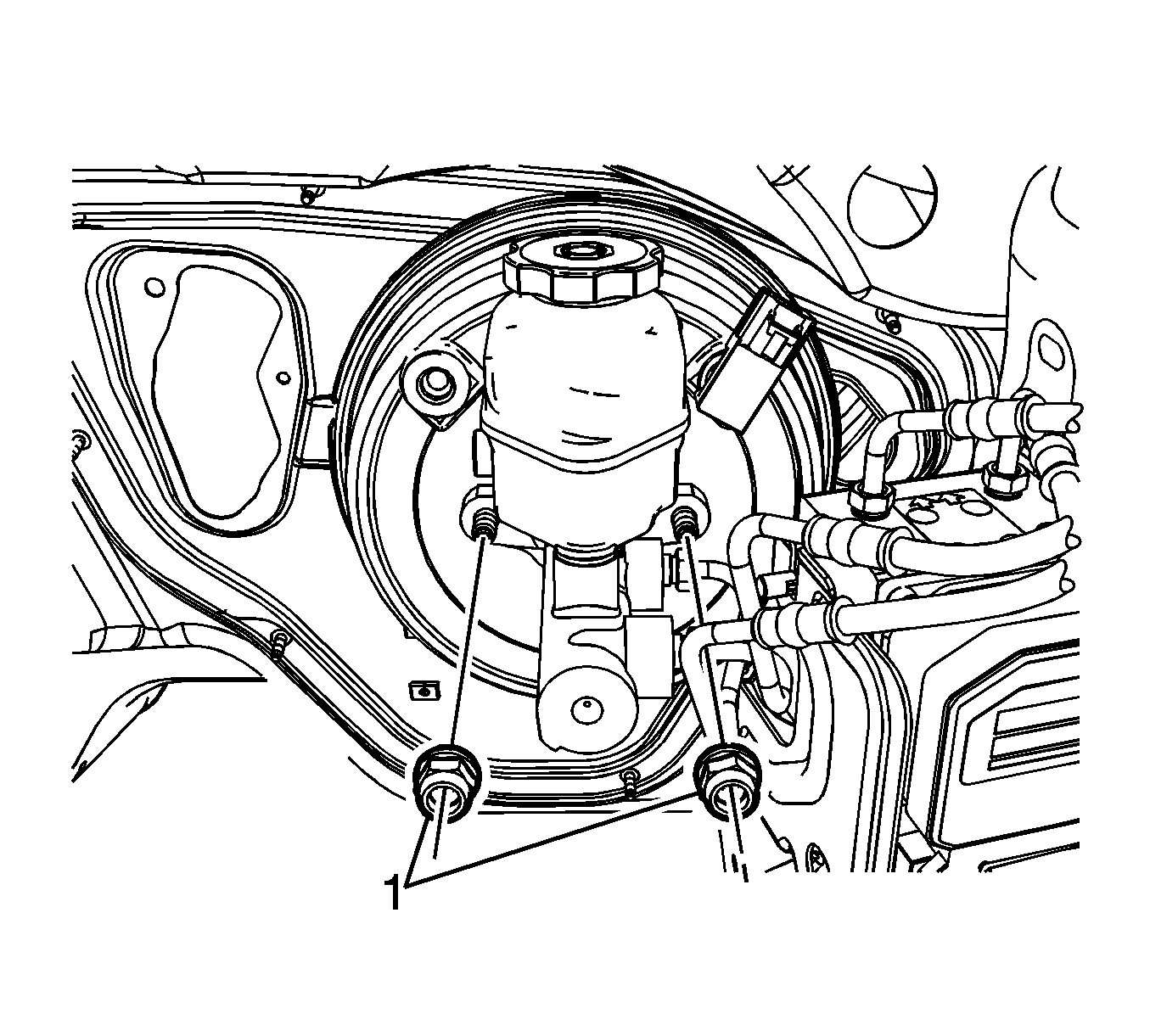
- Remove the master cylinder nuts (1).
- Without disconnecting the brake pipes, remove and position aside the brake master cylinder.
- Wrap a shop cloth around the inboard stud on the vacuum power brake booster to protect the stud threads.
- Install the J-22805-B Brake Booster Holder to the opposite vacuum power brake booster stud and secure with a master cylinder nut.
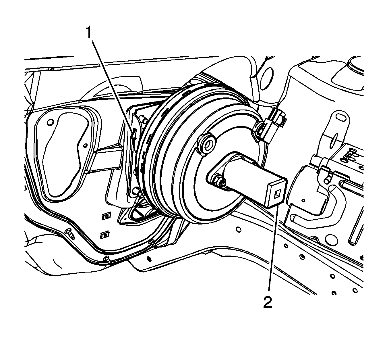
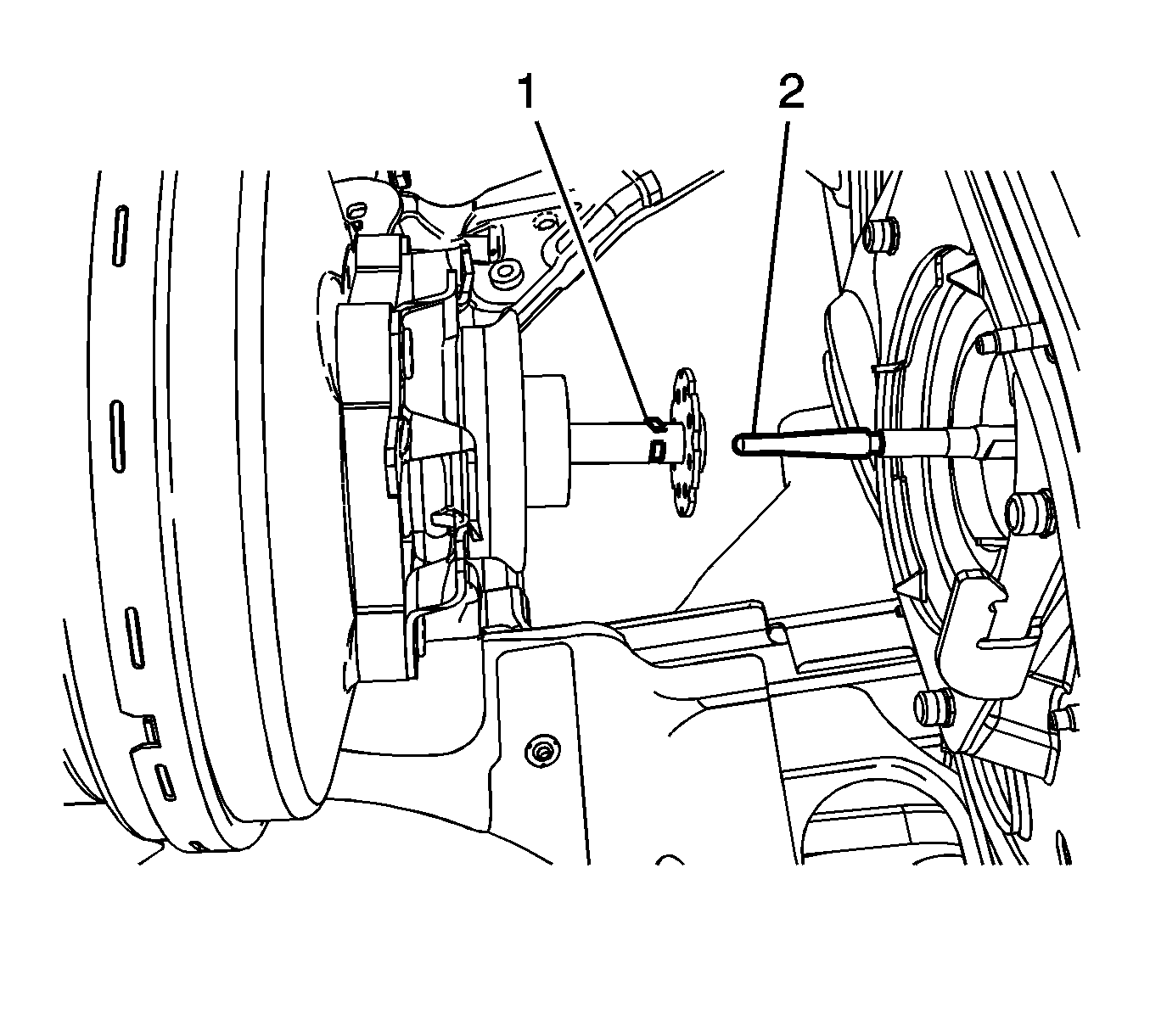
- Levering against the inboard power vacuum brake booster stud, press the vacuum power brake booster locking tab (1) and rotate the J-22805-B Brake Booster Holder (2) counter clockwise.
- Carefully pull the vacuum booster forward slightly and support the vacuum booster to access the brake booster pushrod retaining clip.
- Release the retaining clip (1) and disengage the power vacuum brake booster input rod from the brake booster pushrod (2).
- Remove the vacuum power brake booster.
Secure the master cylinder with heavy mechanics wire or equivalent.
Installation Procedure
- Install the vacuum power brake booster.
- Release the retaining clip (1) and engage the power vacuum brake booster input rod to the brake booster pushrod (2).
- Press the retaining clip into position on the brake booster pushrod
- Position the power vacuum brake booster to the cowl.
- Press the vacuum power brake booster locking tab (1) while rotating the J-22805-B Brake Booster Holder (2) clockwise.
- Remove the J-22805-B Brake Booster Holder from the vacuum power brake booster and discard the master cylinder nuts.
- Install the master cylinder to the vacuum power brake booster.
- Install new master cylinder nuts (1) and tighten to 33 N·m (24 lb ft).
- Connect the vacuum power brake booster check valve and hose assembly (1).
- Connect the vacuum power brake booster vacuum sensor electrical connector.
- Connect the brake fluid level switch electrical connector.
- Install the heater pipe assembly to the throttle body. Refer to Heater Pipes Replacement.
- Install the air cleaner outlet duct. Refer to Air Cleaner Outlet Duct Replacement for the 3.5L engine or Air Cleaner Outlet Duct Replacement for the 3.9L engine.
- Install the intake manifold cover. Refer to Intake Manifold Cover Replacement for the 3.5L engine or Intake Manifold Cover Replacement for the 3.9L engine.


Ensure the locking tab is fully engaged in the vacuum brake booster mounting plate.

Caution: Refer to Fastener Caution in the Preface section.

