For 1990-2009 cars only
Removal Procedure
- Relieve the fuel system pressure. Refer to Fuel System Diagnosis .
- Disconnect the negative battery cable.
- Remove the air filter, resonator, and the snorkel assembly. Refer to Air Cleaner Assembly Replacement .
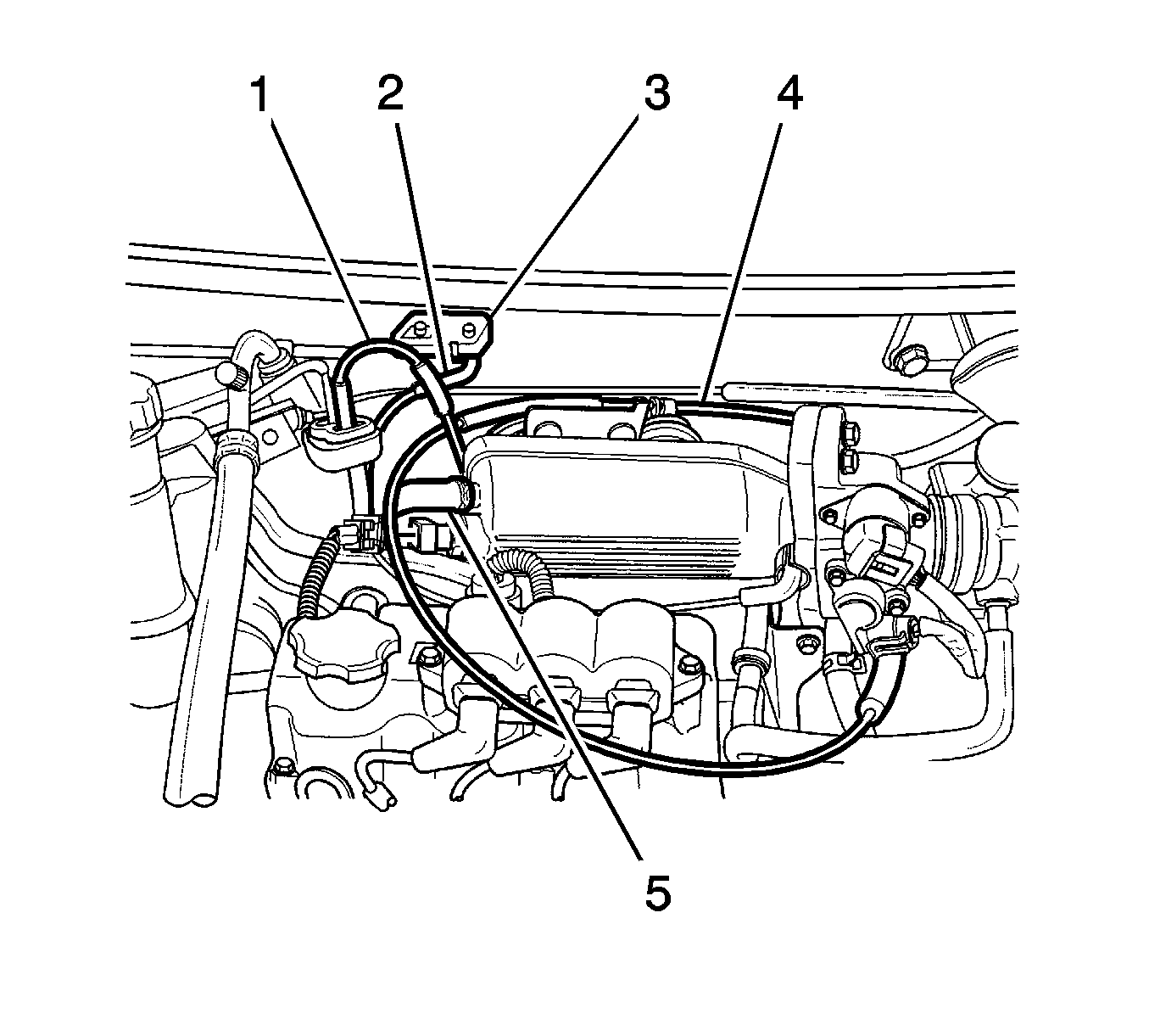
- Remove the surge tank cap (1).
- Disconnect the lower radiator hose and drain the coolant. Refer to Cooling System Draining and Filling .
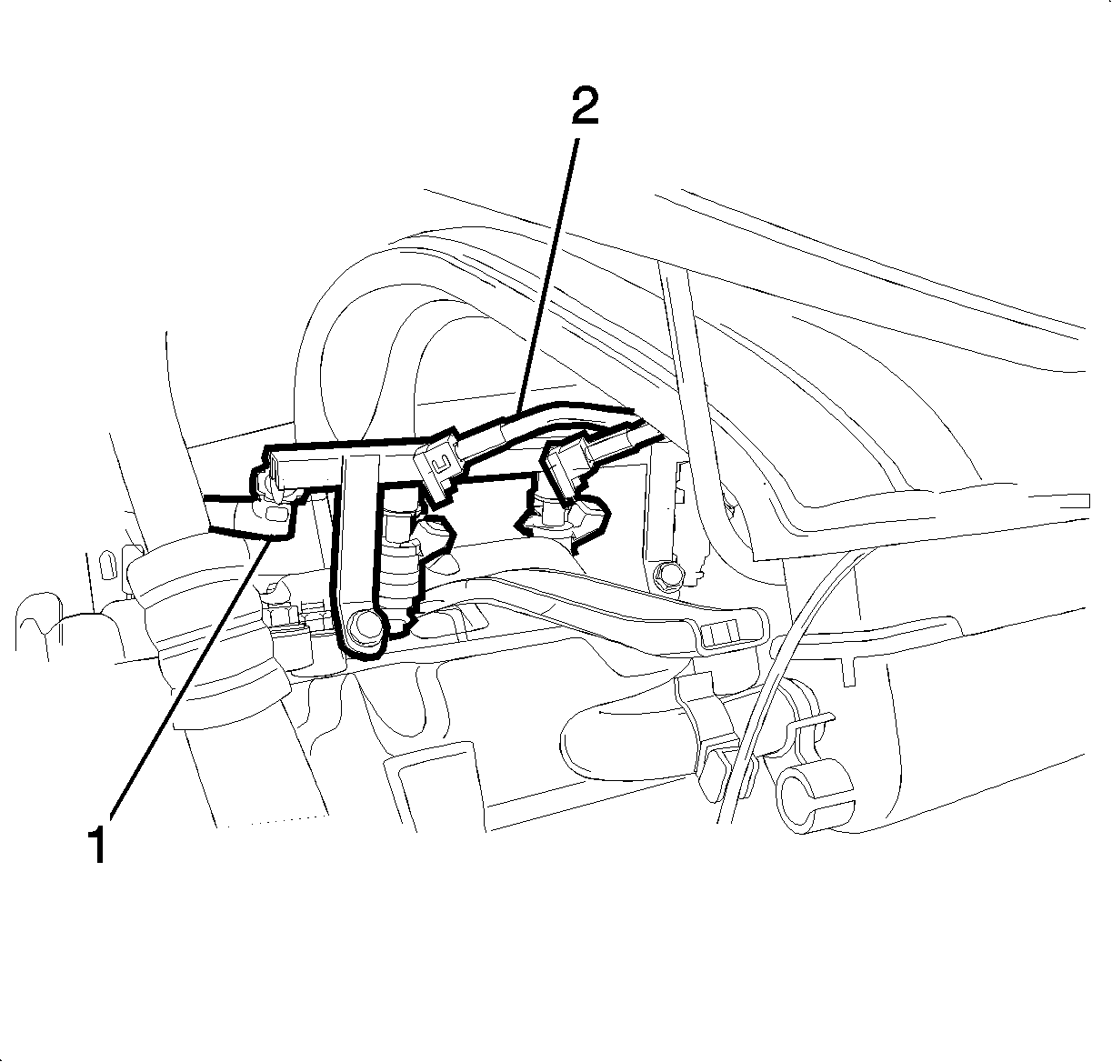
- Disconnect the fuel injector wire connectors (1) and fuel line inlet hose (2).
- Disconnect the throttle cable (4).
- Disconnect the manifold absolute pressure (MAP) sensor connector (3).
- Disconnect the canister solenoid connector (1).
- Disconnect the brake booster vacuum hose (5).
- Disconnect the MAP sensor vacuum hose (2).
- Disconnect the ignition wires (1) from the spark plugs and distributor cap.
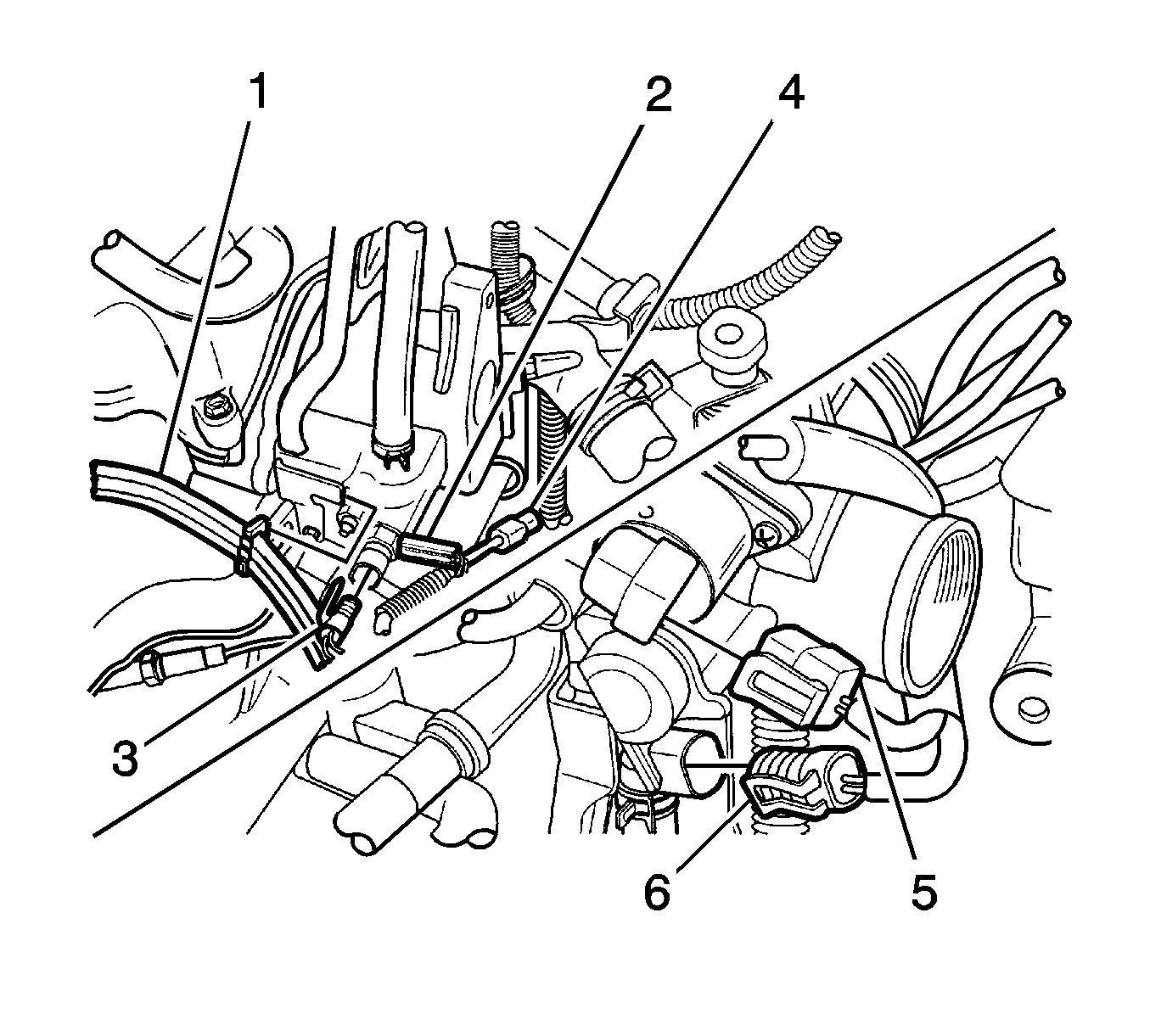
- Disconnect the engine coolant temperature (ECT) sensor connector (2).
- Disconnect the coolant temperature sensor connector (3).
- Disconnect the oxygen sensor connector (4).
- Disconnect the idle air control (IAC) valve connector (5).
- Disconnect the throttle position (TP) sensor connector (6).
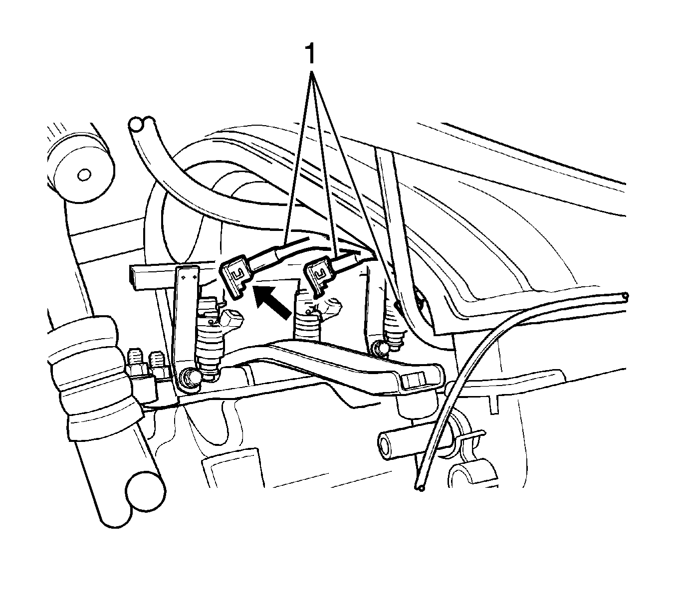
- Disconnect the fuel injector wire connector (1).
- Disconnect the distributor optical sensor connector.
- Remove the exhaust gas recirculation (EGR) solenoid.
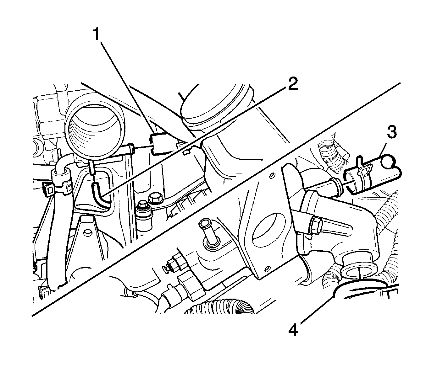
- Disconnect the throttle body coolant outlet hose (1).
- Disconnect the evaporative emission (EVAP) canister vacuum tube (2).
- Disconnect the upper radiator hose from the thermostat housing (3).
- Disconnect the heat core inlet hose from the thermostat housing (4).
- Disconnect the EGR solenoid vacuum tube.
- Remove the timing belt. Refer to Timing Belt Replacement .
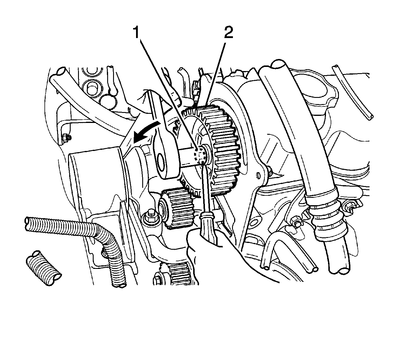
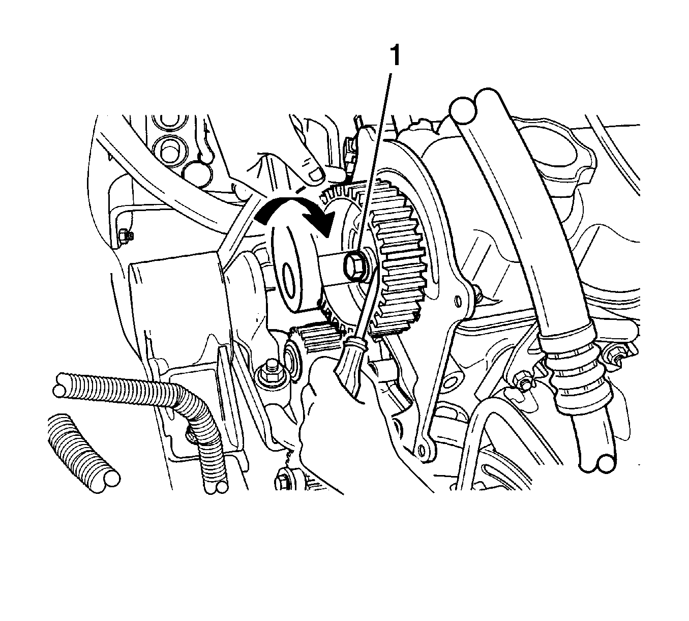
- Remove the camshaft gear bolt (1).
- Remove the camshaft gear from the camshaft (2).
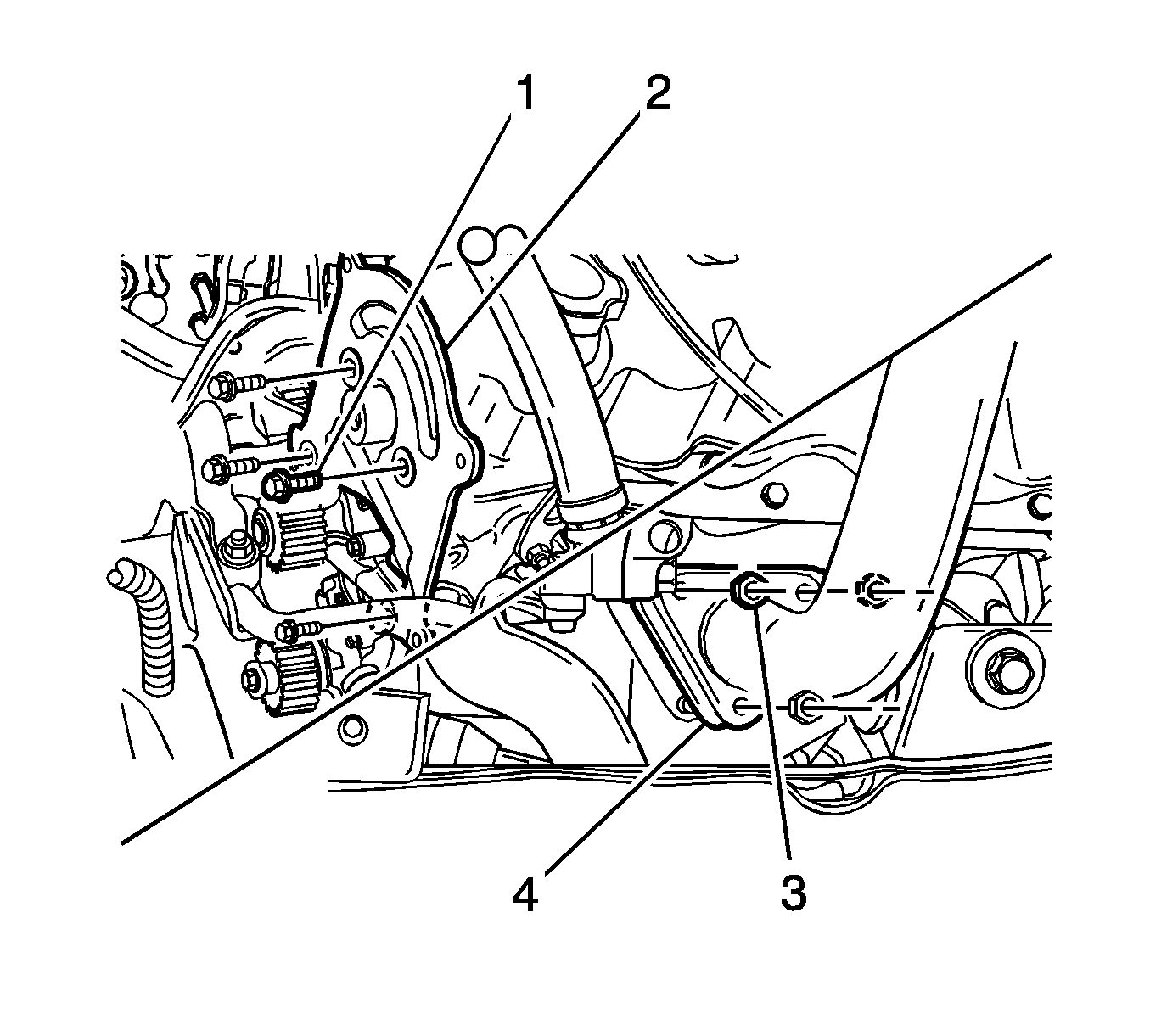
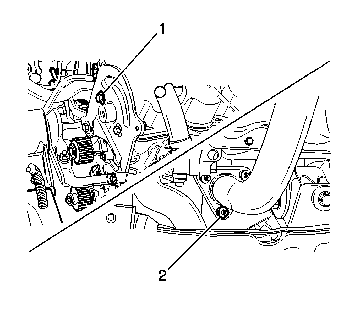
- Remove the timing belt rear cover bolts (1).
- Remove the rear cover from the cylinder head and block (2).
- Remove the front exhaust nuts (3) and the gasket (4).
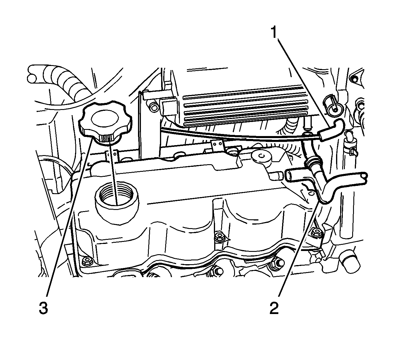
- Disconnect the MAP sensor vacuum tube (1).
- Disconnect the positive crankcase ventilation (PCV) hose and valve (2).
- Remove the oil filler cap (3).
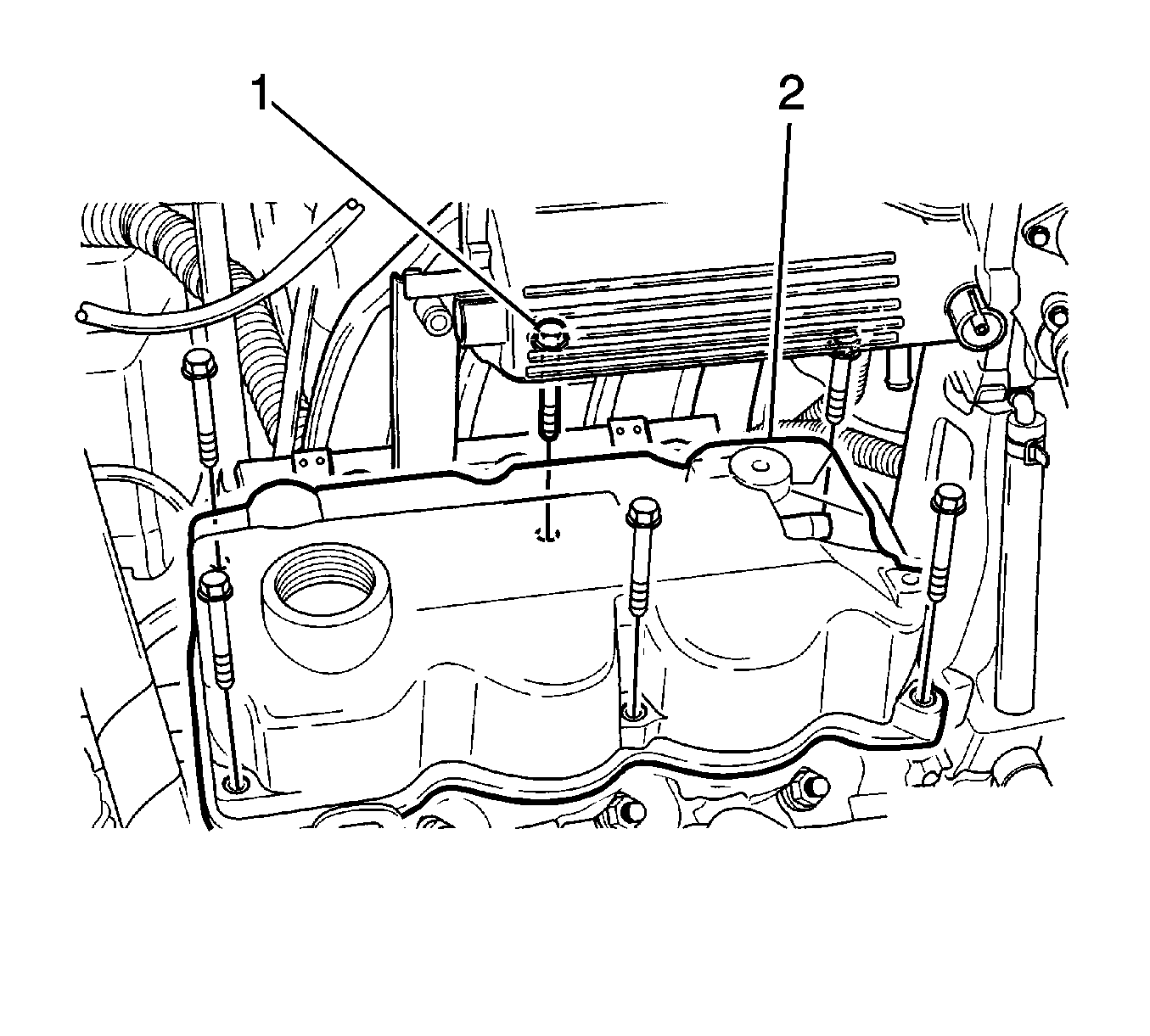
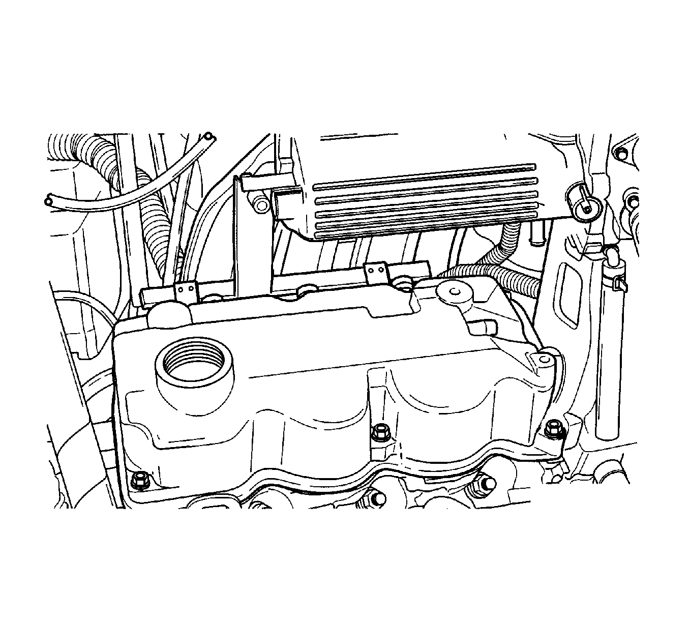
- Remove the cylinder head cover hexagon bolts (1).
- Remove the cylinder head cover with gasket (2).
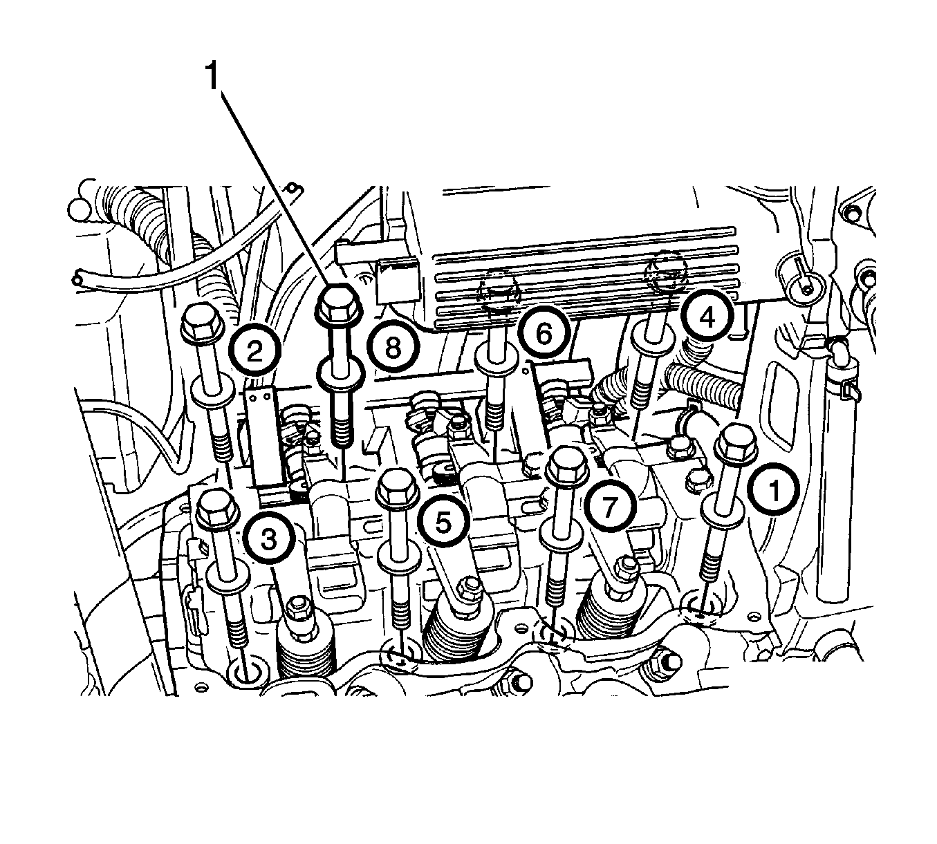
- Gradually loosen all of the cylinder head bolts in the sequence shown.
- Remove the cylinder head bolts (1).
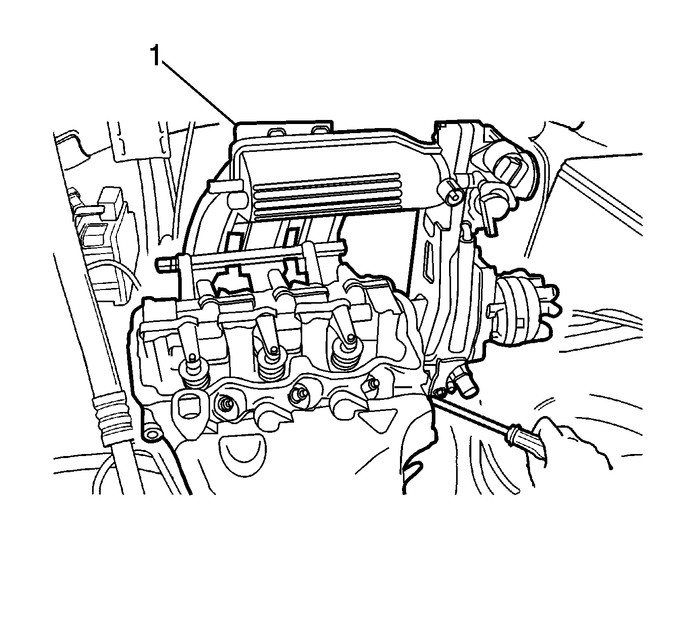
- Remove the cylinder head assembly from the engine block, with the intake/exhaust manifold, throttle body, distributor housing and cylinder head gasket (1).
- Inspect the cylinder head gasket for damage.
- Clean the gasket surfaces of the cylinder head and the engine block.
- Clean the cylinder head bolts.
Caution: Refer to Safety Glasses Caution in the Preface section.
Caution: Refer to Relieving Fuel Pressure Caution in the Preface section.
Caution: Refer to Battery Disconnect Caution in the Preface section.

Caution: Valve springs can be tightly compressed. Use care when removing the retainers and plugs. Personal injury could result.
Installation Procedure
- Install new cylinder head gasket.
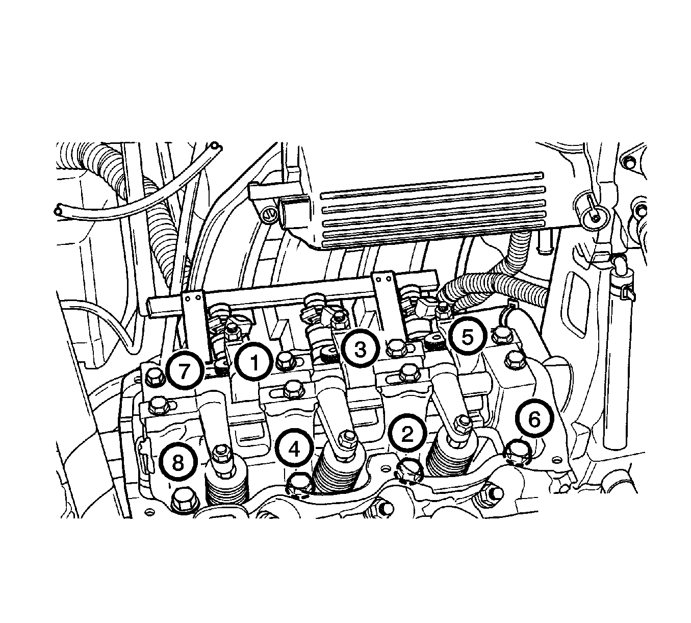
- Install the cylinder head and bolts in the sequence shown.
- Install the cylinder head cover, gasket and bolts.
- Install the oil filler cap (3).
- Connect the PCV hose and valve (2).
- Connect the MAP sensor vacuum tube (1).
- Install the front exhaust pipe, gasket, and nuts (1).
- Install the timing belt rear cover and bolts (2).
- Install the camshaft gear and bolt (1).
- Install the timing belt. Refer to Timing Belt Replacement .
- Connect the EGR solenoid vacuum tube.
- Connect the heater core inlet hose to the thermostat housing (4).
- Connect the upper radiator hose to the thermostat housing (3).
- Connect the EVAP canister vacuum tube (2).
- Connect the throttle body coolant outlet hose (1).
- Install the EGR solenoid.
- Connect the distributor optical sensor connector.
- Connect the TP sensor connector (6).
- Connect the IAC valve connector (5).
- Connect the oxygen sensor connector (4).
- Connect the coolant temperature sensor connector (3).
- Connect the ECT sensor connector (2).
- Connect the ignition wires (1) from the spark plugs and distributor cap.
- Connect the MAP sensor vacuum hose (2).
- Connect the brake booster vacuum hose (5).
- Connect the canister solenoid connector (1).
- Connect the MAP sensor connector (3).
- Connect the throttle cable (4).
- Connect the fuel injector wire connectors (1) and fuel line inlet hose (2).
- Install the surge tank cap (1).
- Connect the lower radiator hose (2) and fill the coolant. Refer to Cooling System Draining and Filling .
- Install the air filter, resonator, and the snorkel assembly. Refer to Air Cleaner Assembly Replacement .
- Connect the negative battery cable.
Notice: Refer to Fastener Notice in the Preface section.
Tighten
Tighten the cylinder head bolts to 85-90 N·m (63-66 lb ft).
Tighten
Tighten the cylinder head cover bolts to 9-12 N·m (80-106 lb in).

Tighten
Tighten the front exhaust pipe nuts to 25-35 N·m (18-25 lb ft).
Tighten
Tighten the timing belt rear cover bolts to 9-12 N·m (80-106 lb in).
Tighten
Tighten the camshaft gear bolt to 50-60 N·m (36-44 lb ft).


