Tools Required
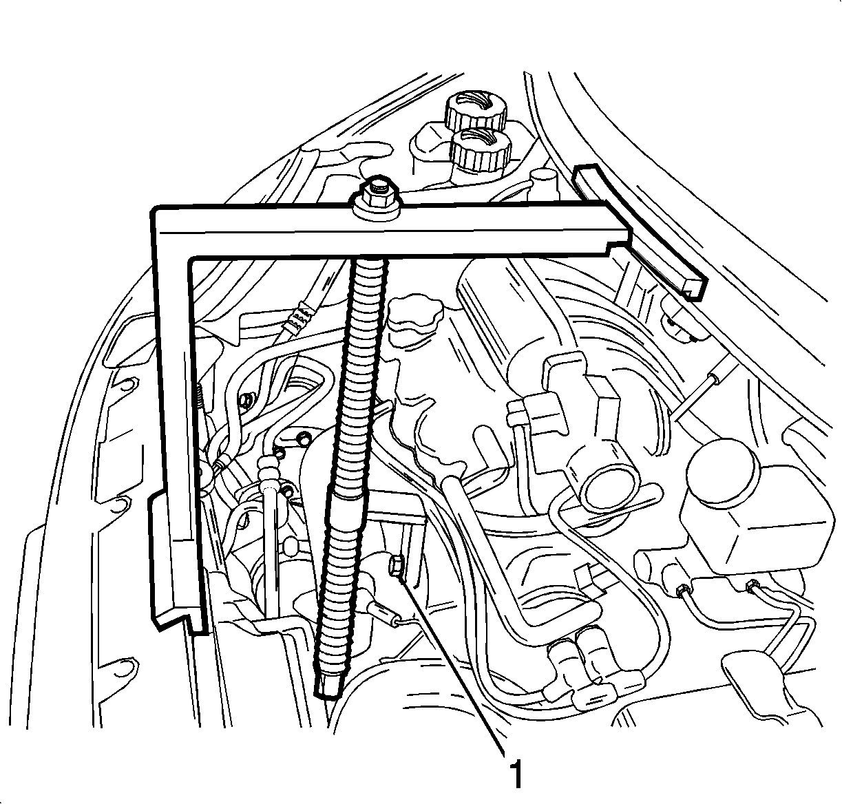
EN46567 (DW110-020-A) Engine Assembly Support Fixture
Removal Procedure
- Install the EN46567 (1).
- Remove the air inlet grill panel weatherstrip.
- Remove the exhaust manifold heat shield.
- Position the EN46567 (1) on the air inlet grill panel and the front upper panel on the center.
- Tighten the engine fixture joint with a bolt after removing exhaust manifold bolt.
- Remove the coolant surge tank. Refer to Radiator Surge Tank Replacement .
- Remove the right headlamp. Refer to Headlamp Replacement .
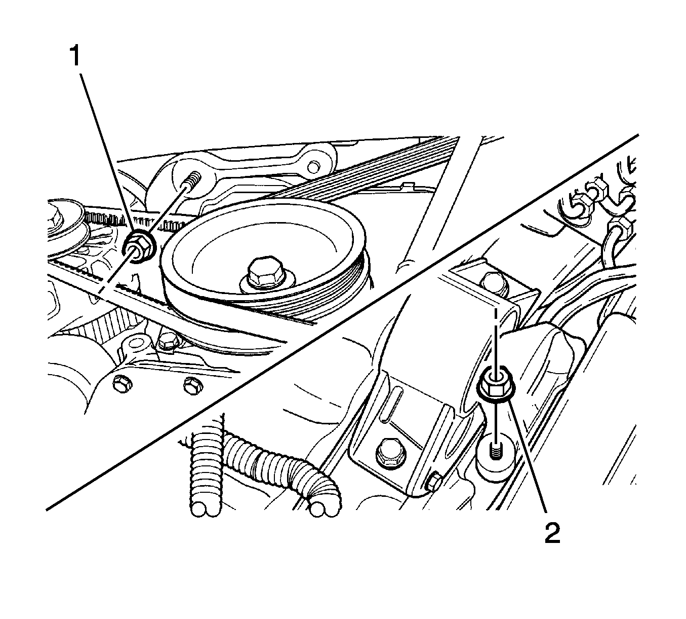
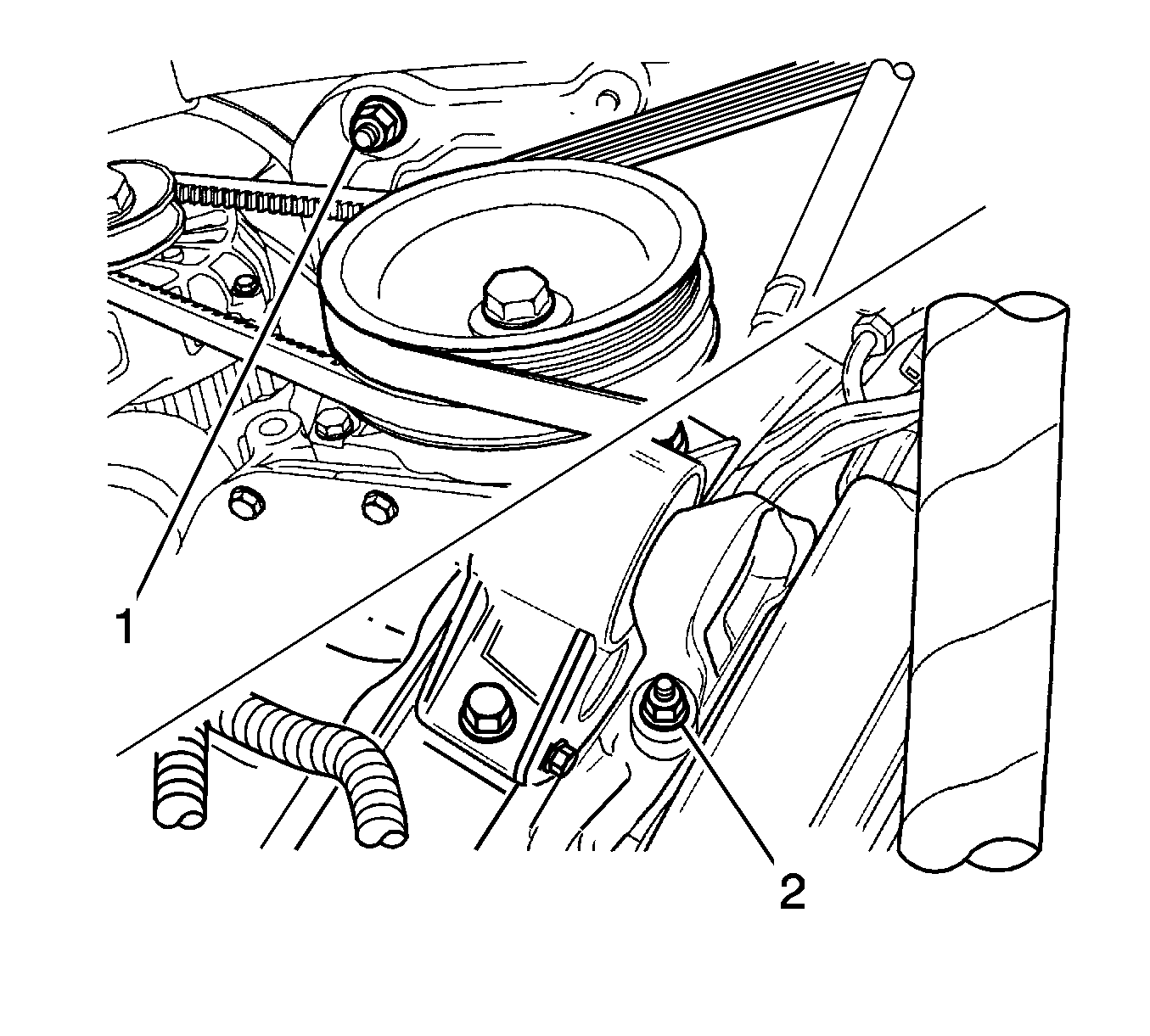
- Remove the intermediate bracket nut from the lower vehicle (1).
- Remove the intermediate bracket nut from the upper vehicle (2).
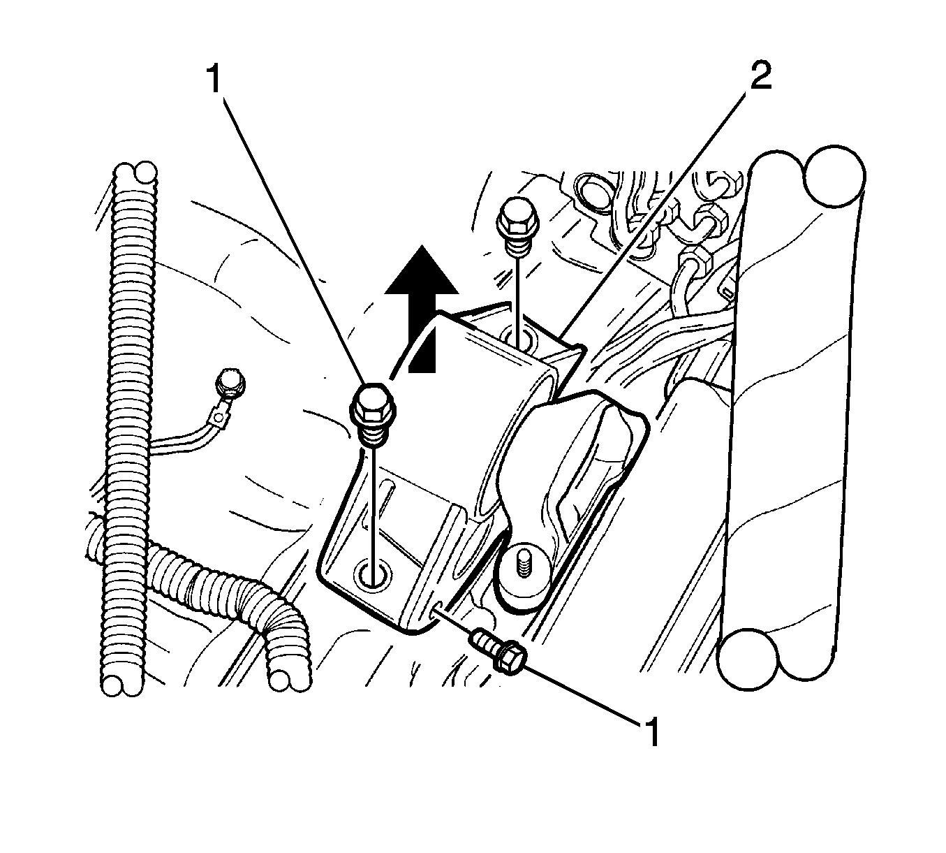
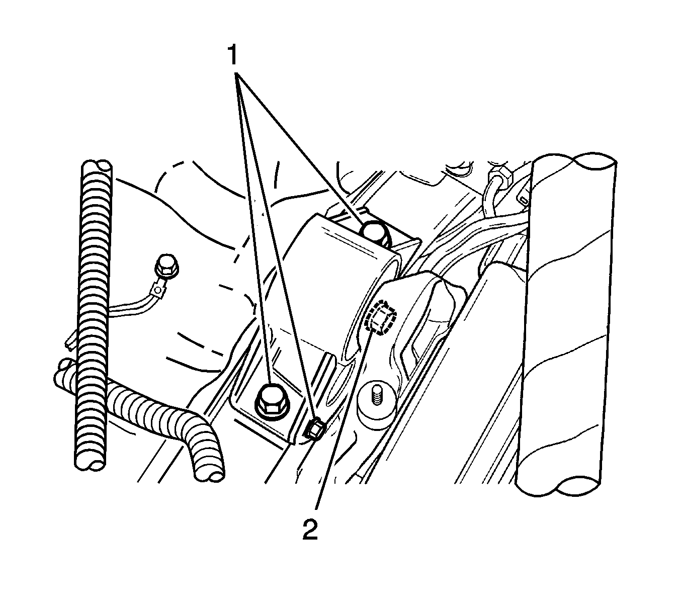
- Remove the engine mount damping block bolts (1).
- Remove the engine mount damping block assembly with the intermediate bracket attached.
- Remove the engine mount damping block assembly from the wheelhouse and engine mount upper bracket (2).
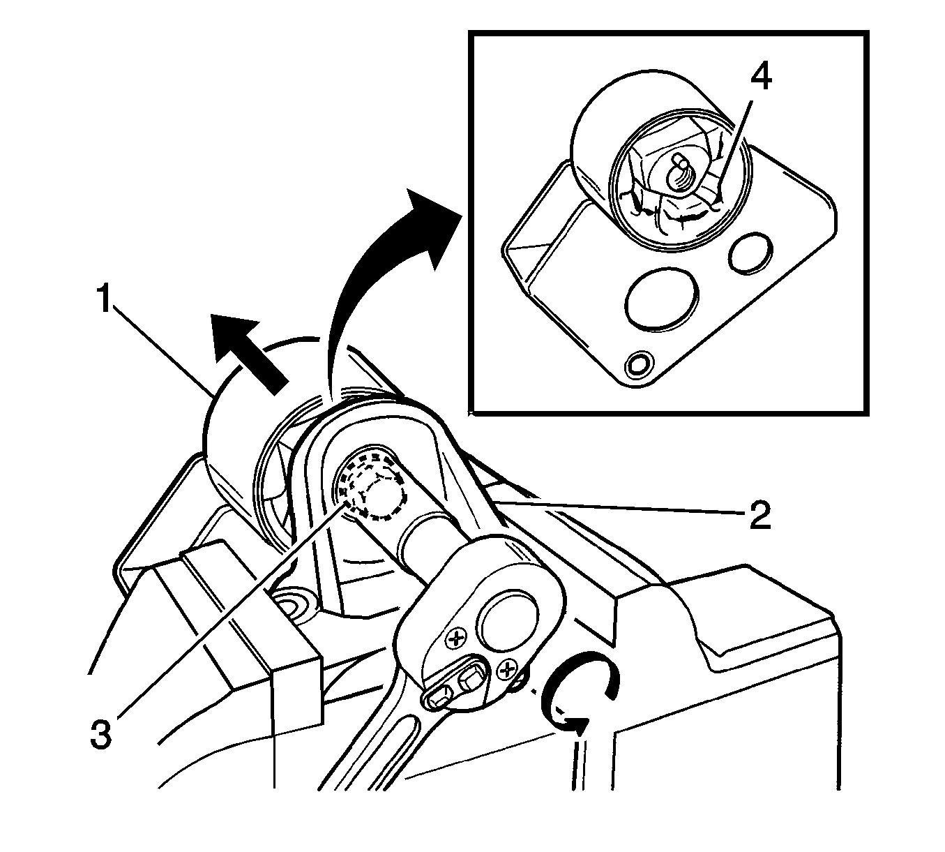
- Vice the intermediate bracket (3).
- Remove the intermediate bracket bolt (2).
- Remove the engine mount damping block from the intermediate bracket (1).
- Inspect the damping block (4) for the crack, hardening or damaged.
Notice: Broken engine mountings can cause misalignment of certain drive-train components. Misalignment of drive-train components causes eventual destruction of the drive-train components.
If one engine mount breaks, the rest of the engine mounts will have increased stress put on them. This could cause the rest of the engine mounts to break.Notice: When raising or supporting the engine for any reason, do not use a jack under the oil pan, any sheet metal, or crankshaft balancer. Jacking against the oil pan may cause it to crack or break.
Notice: Loosen the engine support fixture bolt in order to lower the engine slightly and allow the engine mount damping block bolts to be removed. If the engine mount damping block bolts are loosened without lowering the engine assembly support fixture, the engine mount damping block bolts could be damaged.
Important: Loosen the bolts adjusting the engine assembly support fixture up and down slightly.
Installation Procedure
Notice: Refer to Fastener Notice in the Preface section.
- While intermediate bracket in vise, install engine mount damping block and bolt (2).
- Install engine mount damping block assembly and bolts (1) on to the wheelhouse and engine mount upper bracket.
- Install the lower/upper engine mount intermediate bracket nuts (1, 2).
- Install the right headlamp. Refer to Headlamp Replacement .
- Install the coolant surge tank. Refer to Radiator Surge Tank Replacement .
- Remove the EN46567 (1).
- Install the exhaust heat shield and bolt.
- Install the air inlet grill panel weatherstrip.
Tighten
Tighten the intermediate bracket bolt to 72-88 N·m (53-65 lb ft).
Tighten
Tighten the engine mount damping block bolts to 45-55 N·m (33-41 lb ft).
Tighten
Tighten the lower/upper engine mount intermediate bracket nuts to 60-70 N·m (44-52 lb ft).

