Tools Required
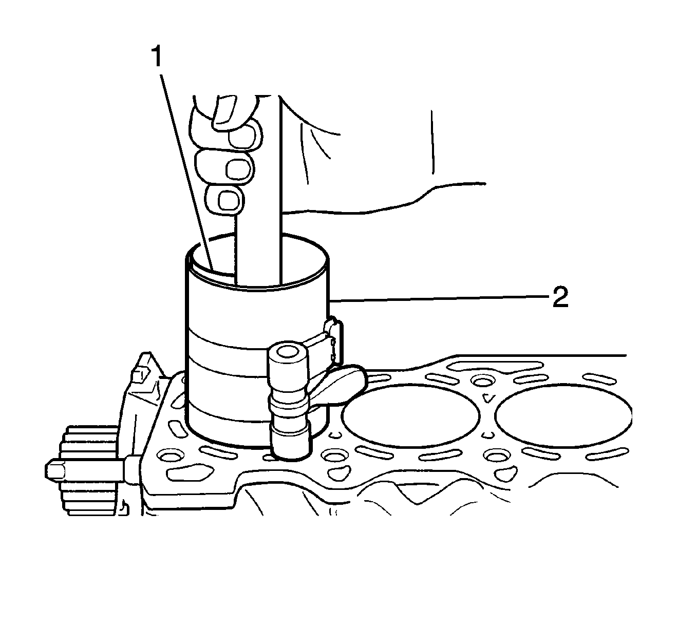
09916-77310 Piston Compressor
- Install the crankshaft thrust bearing and upper main bearing, then install the crankshaft to the crankshaft journal.
- Coat the engine oil in the oil groove (2) and install the crankshaft thrust bearings to place the oil groove in the outer part of the journal portion (1).
- Install the upper crankshaft main bearings to the crankshaft journal with the bearing oil port (2) to direction of the oil filter (1). Install the lower crankshaft bearings identically when installing the bearing cap.
- Position the crankshaft on the engine block journal.
- Install the lower crankshaft main bearing to the crankshaft journal part (3).
- Install the bearing cap to the crankshaft journal part with the bolts (2) according to the sequence (1).
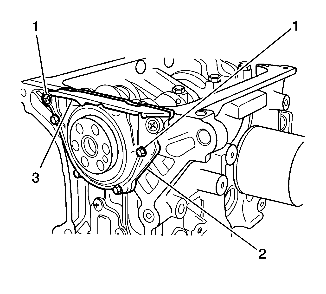
- Install the oil seal housing gasket (2).
- Install the crankshaft rear oil seal housing after coating engine oil to the oil seal lip (3).
- Cut them with scraper, if the gasket edges are bulged.
- Install the bolts and screws (1).
- In case of the crankshaft unit repair, install the oil pump gasket (1).
- Insert the hose in the crankshaft to prevent damage on the oil pump seal when installing the oil pump (4).
- Install the oil pump housing (3) with the bolts (2).
- Cut them with scraper, if the gasket edges are bulged.
- Assemble the piston and the connecting rod.
- Install the piston pin (2).
- Retain the piston pin with the circlips (1).
- When installing the oil ring, insert the spacer first and 2 rails later (3).
- Install the second compression ring to direct the marked R side upward (2).
- Install the compression ring (1).
- Install 3 rings and position their openings as shown.
- Coat the engine oil to piston, ring, cylinder wall and bearing crank pin of connecting rod.
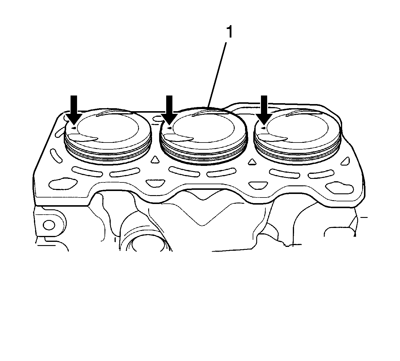
- Position the piston into the cylinder to make the arrow point directly towards the crankshaft pulley (1).
- Confirm the hose inserted in connecting rod stud bolt to prevent the damage of the cylinder wall and the crankshaft bearing crank pin before installing the piston and connecting rod assembly.
- Pucker the piston ring with 09916-77310 and insert the connecting rod and the piston to the cylinder properly. In this time, push 09916-77310 against the engine block and insert the piston lightly (1).
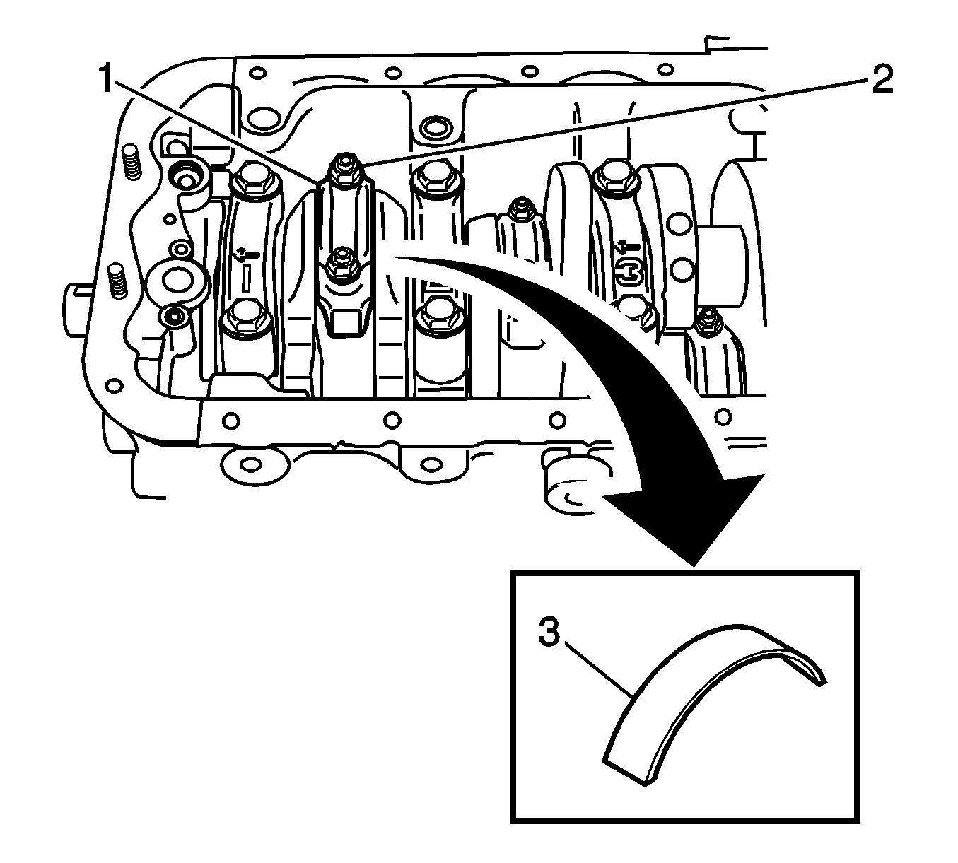
- Install the connecting rod according to the sequence.
- Install the upper connecting rod bearing to the connecting rod bearing journal.
- Install the lower crankshaft main bearing to the crank pin part (3).
- Position the bearing cap on the crankshaft crank pin part to make the arrow point direct toward the crank pulley according to the sequence after positioning the piston on bottom dead center (BDC) (1).
- Tighten the bearing cap nuts (2).
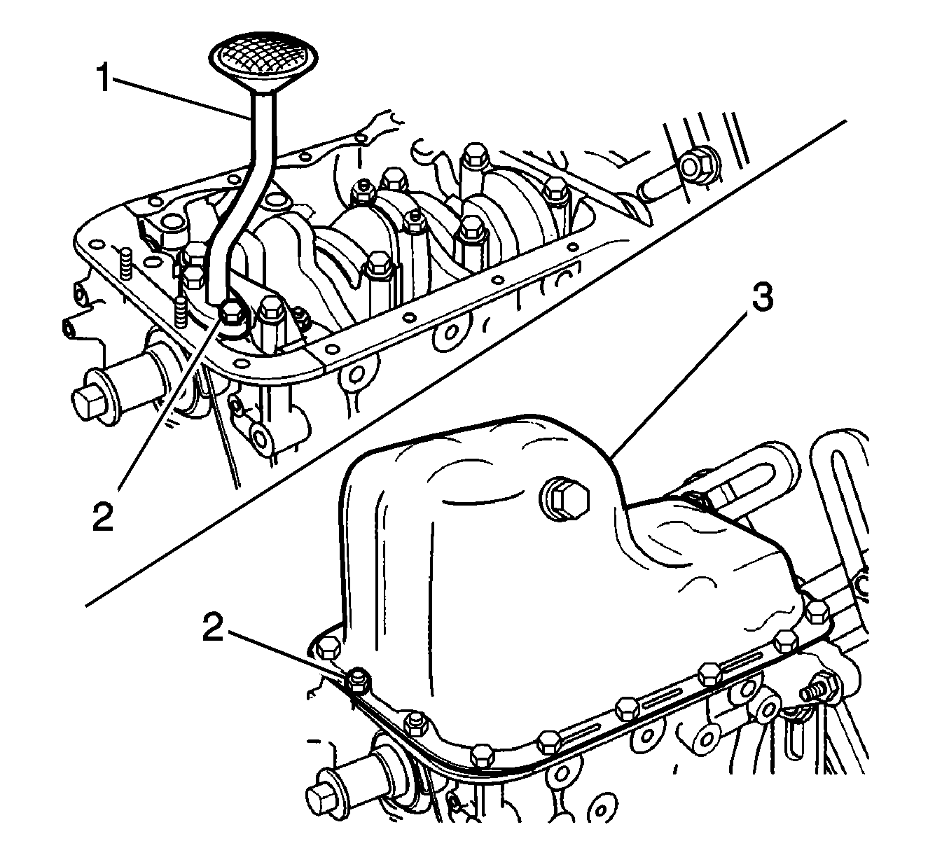
- Install the oil pump pickup tube (1) with the bolts (2).
- Coat the liquefied gasket on the engine block.
- Install the oil pan with the bolts and the nuts (3).
- Install the lower engine mount bracket (3) and the generator with the bolts (1).
- Install the upper engine mount bracket and the generator shackle (2) with the bolts (1).
- Install the generator with the bolts and the nut (3).
- Install the generator belt and adjusting the bolts (2).
- Install the engine mount bracket (4).
- Install the A/C compressor/power steering pump and the bracket with the bolts (1).
- Install the power steering pump bracket (2).
- Install the power steering pump bracket bolt and nut (1) and the adjusting bolts (5).
- Position the A/C compressor into the normal location.
- Install and tighten the compressor bolts (4).
- Install the power steering/air conditioning belt.
- Install the cylinder head with the intake manifold, the exhaust manifold, and distributor/adaptor attached. Refer to Cylinder Head Replacement .
- Install the timing belt and components. Refer to Timing Belt Replacement .
- Install the clutch and the transaxle to the engine, then engine assembly to the engine compartment. Refer to Engine Replacement .
- Refill the engine crankcase with engine oil.
- Refill the engine coolant system. Refer to Cooling System Draining and Filling .
- Bleed the power steering system as necessary. Refer to Power Steering System Bleeding .
- Refill the A/C refrigerant system as necessary. Refer to Refrigerant Recovery and Recharging .
- Refill the transaxle oil as necessary.
- Connect the negative battery cable.
- Start the engine and operate all systems.
- Operate the idle air control valve reset procedure as necessary.
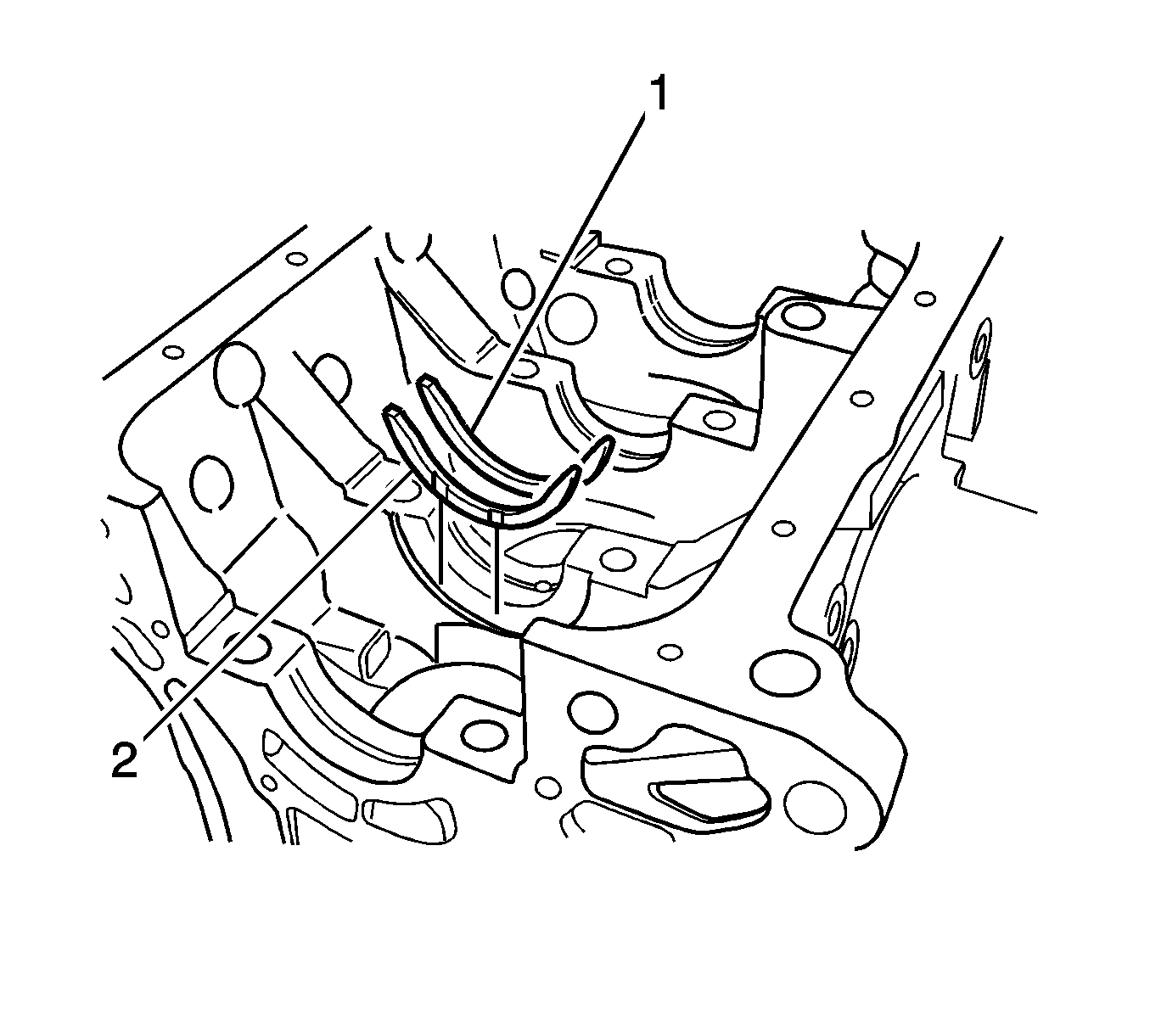
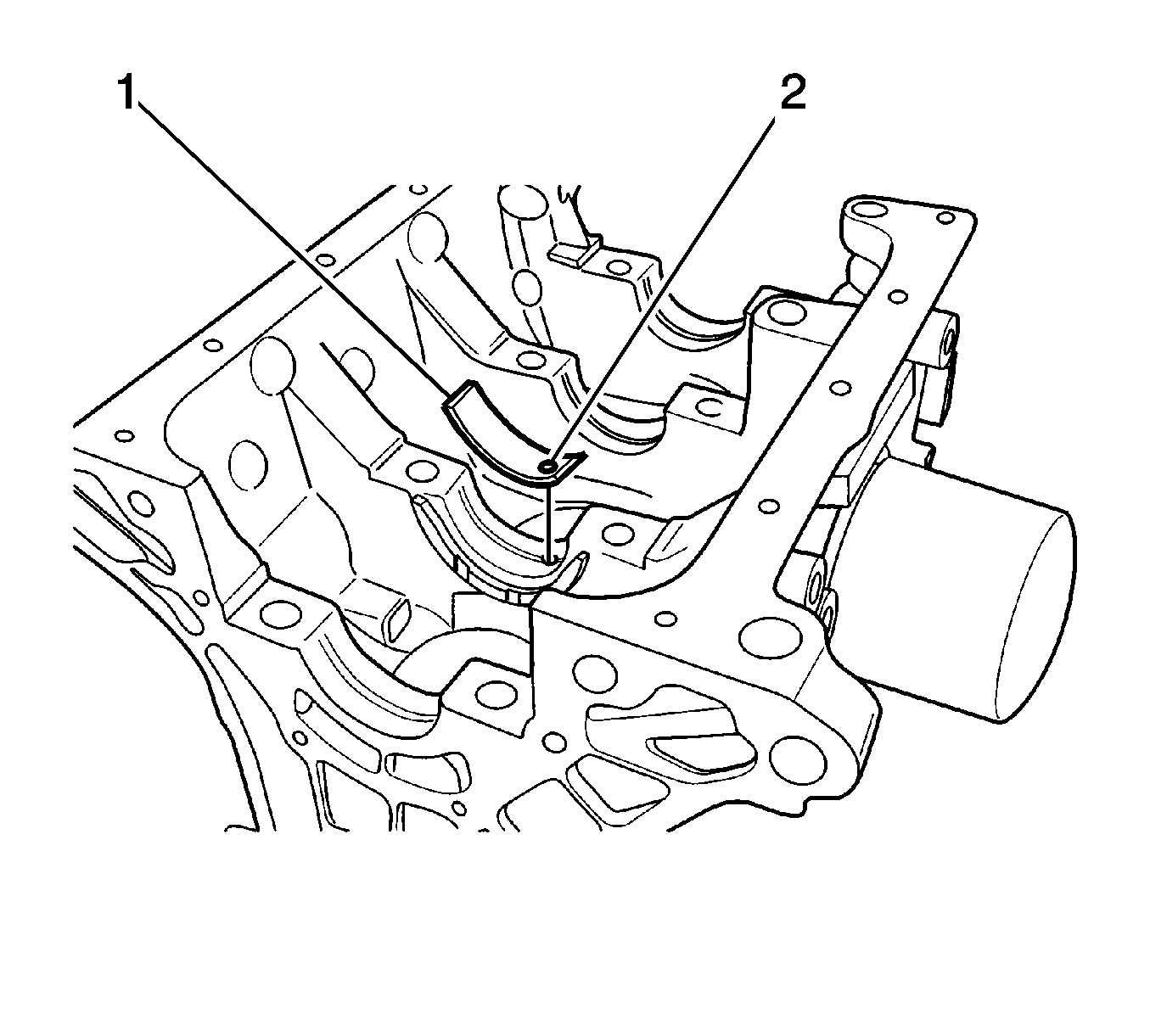
Important: Coat engine oil to the inner surface of bearing, or journal surface of crankshaft - crank pin side when installing bearing.
Notice: Avoid installing the bearing caps incorrectly. Cylinder head and camshaft damage may result.
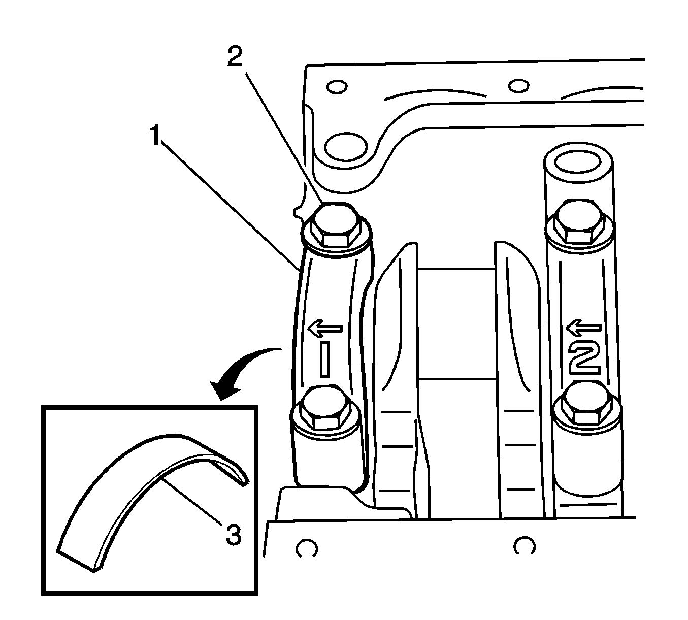
Important: On the bearing cap of the crankshaft journal part, numbers 1-4 are marked in sequence.
Notice: Refer to Fastener Notice in the Preface section.
Tighten
Tighten the bearing cap bolts to 50-60 N·m (36-44 lb ft).
Tighten
| • | Tighten the bolts to 9-12 N·m (80-106 lb in). |
| • | Tighten the screws to 9-12 N·m (80-106 lb in). |
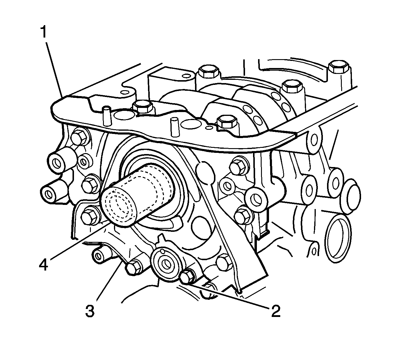
Important: Do not reuse the removed gasket. Replace it with a new one.
Tighten
Tighten the bolts to 9-12 N·m (80-106 lb in).
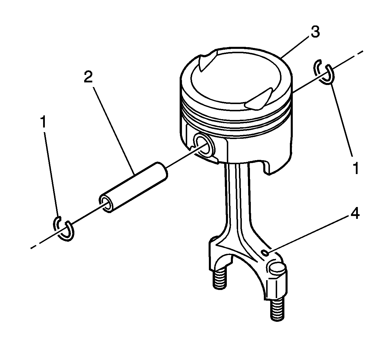
Important: There are assembling directions for the piston and the connecting rod. Direct the piston front mark (3) on the piston head toward the crankshaft pulley and oil hole (4) on the connecting rod toward the exhaust manifold to assemble the piston and the connecting rod.
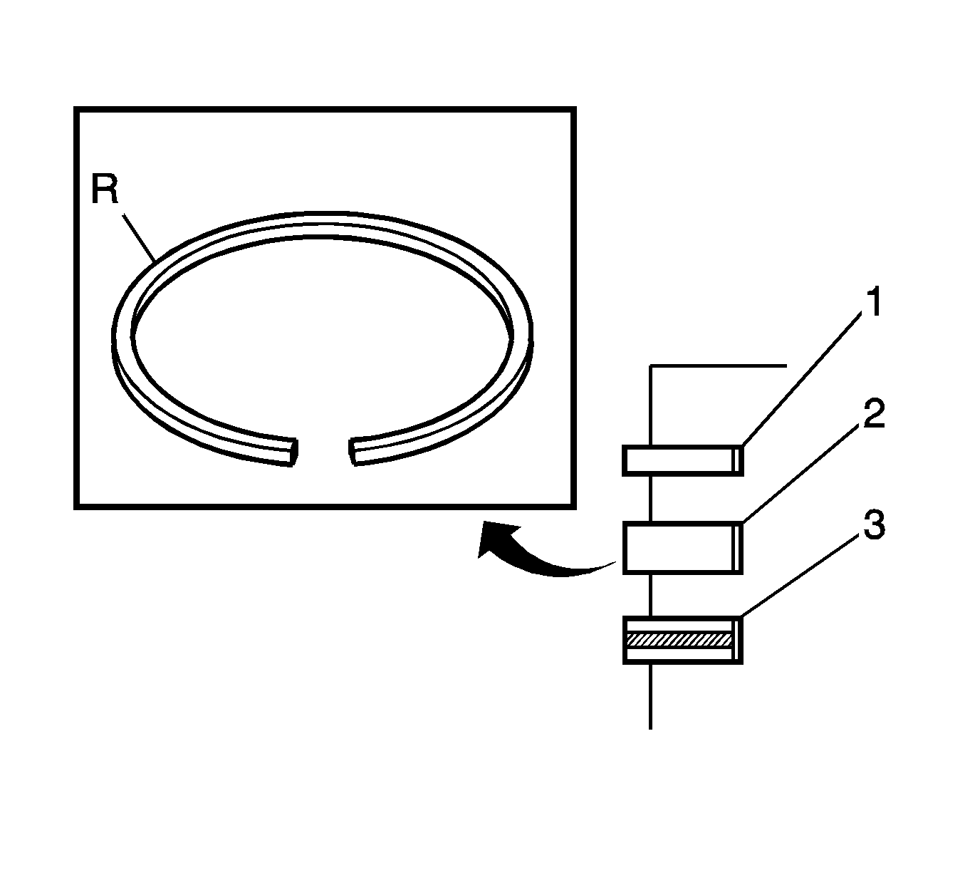
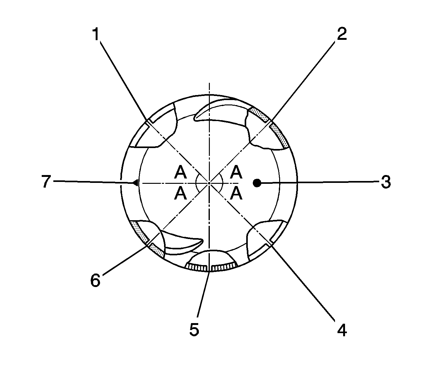
| • | Opening of compression ring No.1 (2). |
| • | Opening of compression ring No. 2 (6). |
| • | Opening of oil ring rail upper rail (1). |
| • | Opening of oil ring spacer (5). |
| • | Opening of oil ring rail lower rail (4). |
| • | Mark (7). |
| • | Piston head (3). |
Notice: Avoid installing the bearing caps incorrectly. Cylinder head and camshaft damage may result.
Tighten
Tighten the bearing cap nuts to 31-35 N·m (23-25 lb ft).
Tighten
Tighten the oil pump pickup tube bolts to 9-12 N·m (80-106 lb in).
Tighten
Tighten the nuts and bolts to 9-12 N·m (80-106 lb in).
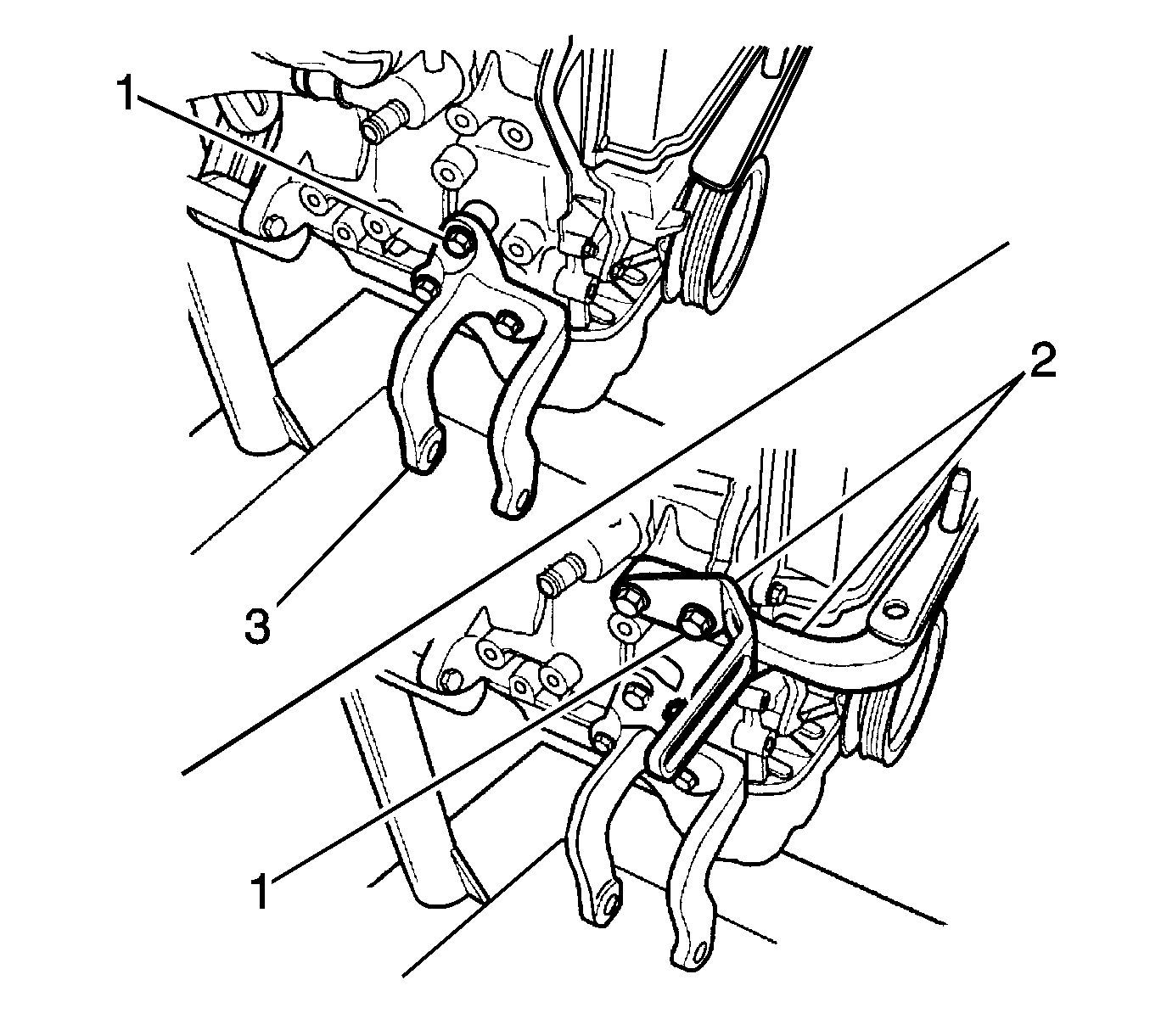
Tighten
Tighten the bolts to 35-41 N·m (25-30 lb ft).
Tighten
Tighten the bolts to 35-41 N·m (25-30 lb ft).
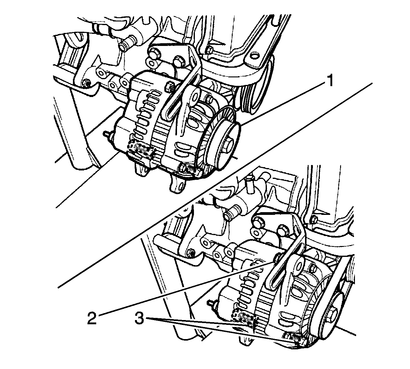
Tighten
Tighten the generator lower bolts and the nut loosely to 18-25 N·m (13-21 lb ft).
Tighten
Tighten the generator belt tension adjusting the bolts to 18-28 N·m (13-21 lb ft).
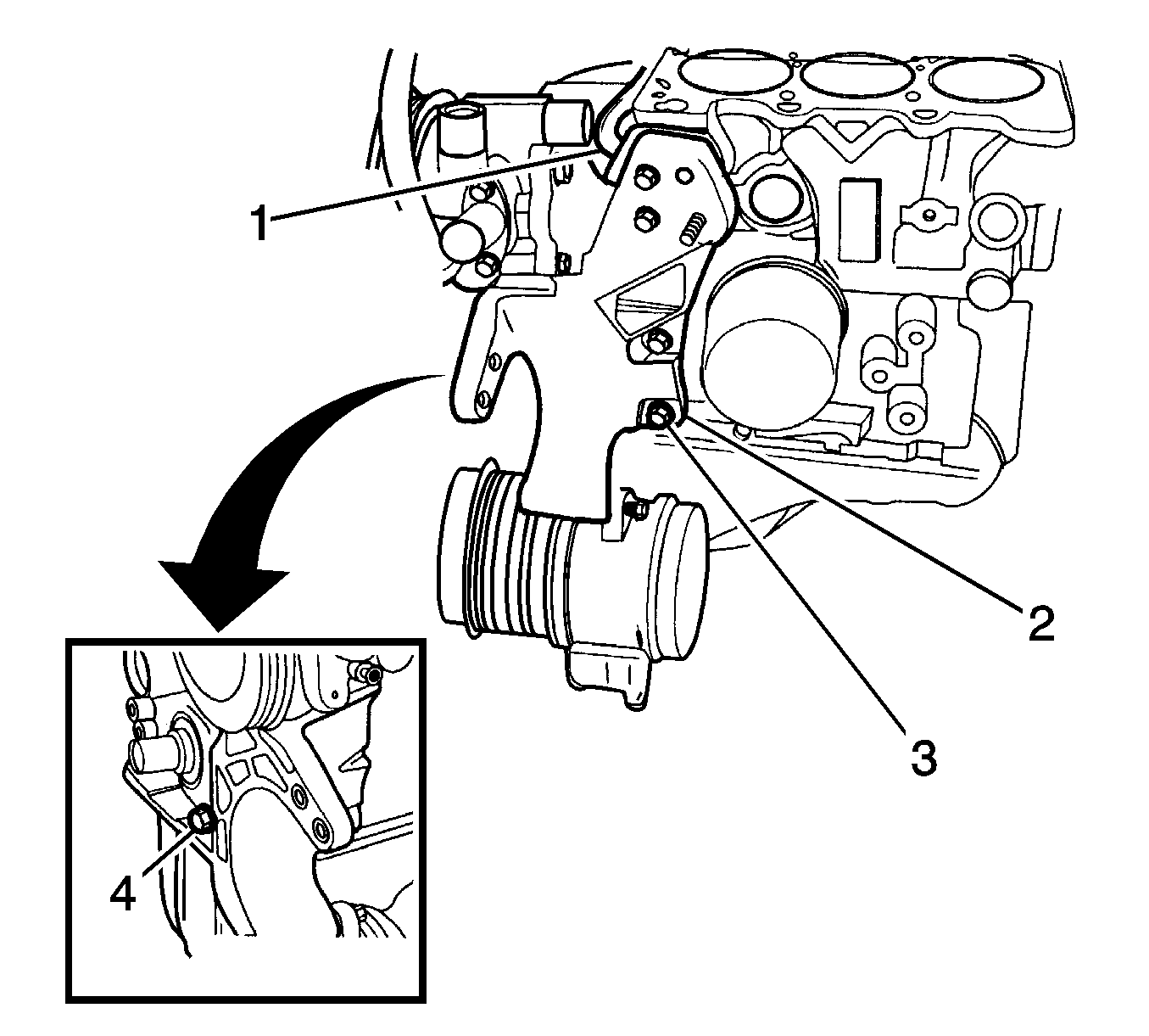
Tighten
| • | Tighten the bracket bolt to 18-22 N·m (13-16 lb ft). |
| • | Tighten the bracket bolts to 35-41 N·m (25-30 lb ft). |
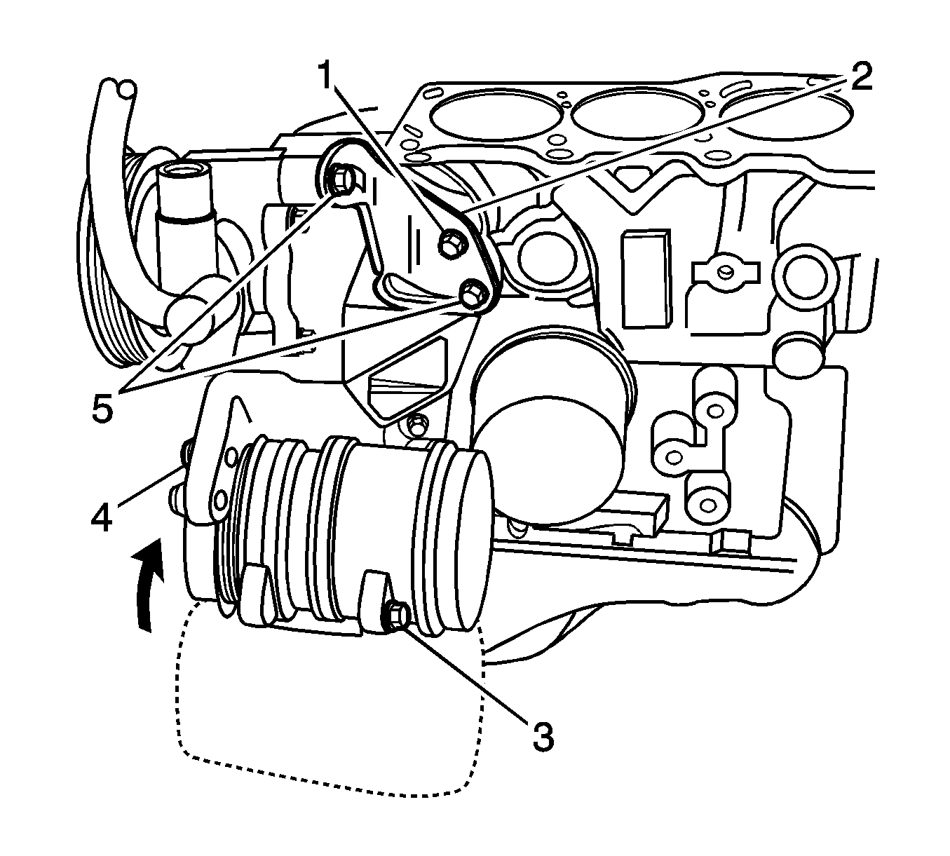
Tighten
| • | Tighten the power steering rear bracket bolt to 18-22 N·m (13-16 lb ft). |
| • | Tighten the adjusting bolt and the power steering rear bracket nut to 20-24 N·m (15-18 lb ft). |
Tighten
| • | Tighten the bolts to 18-22 N·m (13-16 lb ft). |
| • | Tighten the bolt to 20-24 N·m (15-18 lb ft). |
