GM Service Manual Online
For 1990-2009 cars only
Table 1: Operating Conditions
Table 2: Valve Body Components

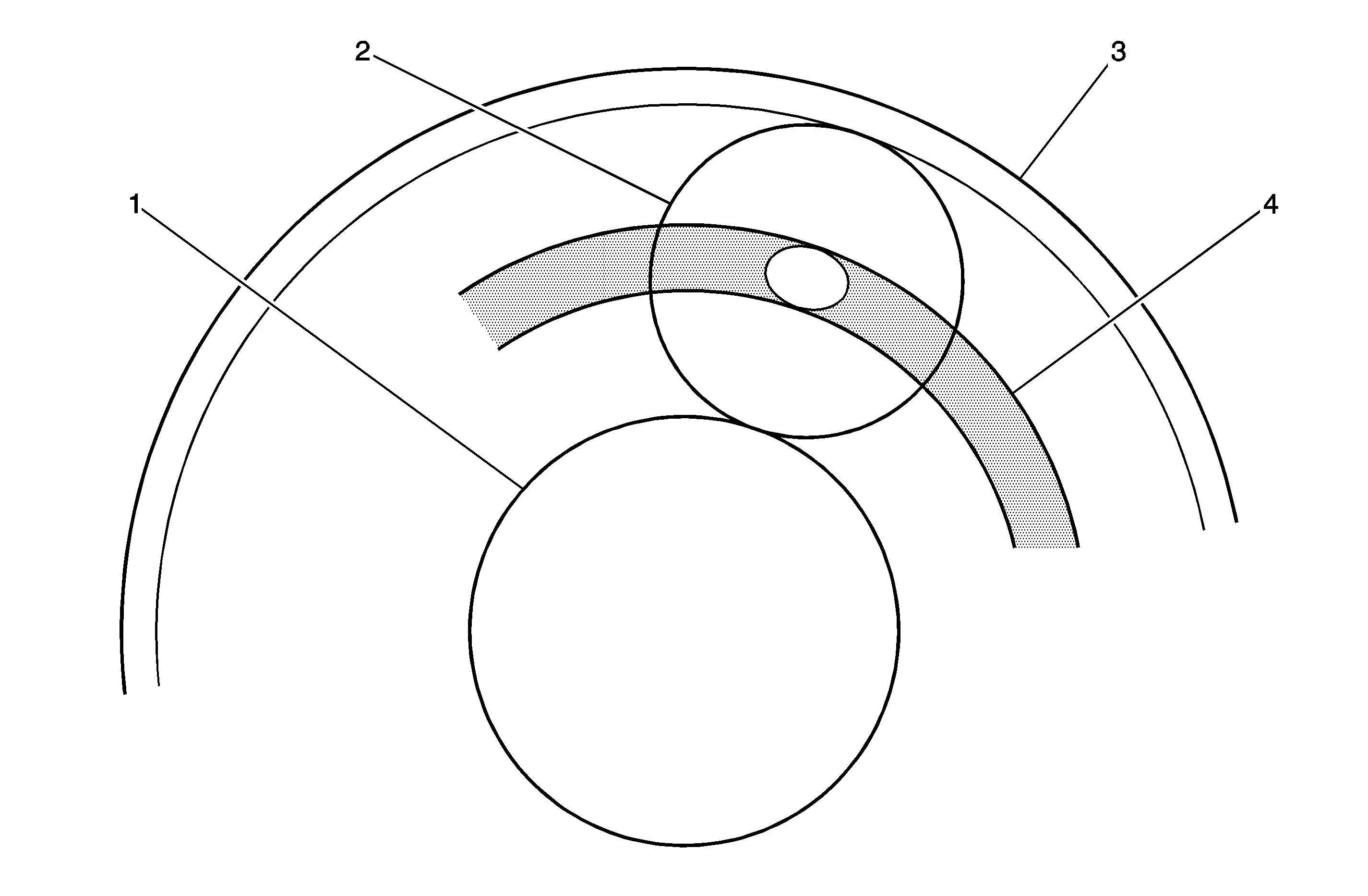
Planetary Gear Unit

Planetary gear unit shifts the gear position to forward, reverse, or neutral while driving. the unit consists of a sun gear, a planetary carrier, and an internal gear. The different engagement patterns of this unit installed in the front and rear operate when driving forward, backward, and shifting


Object Number: 1282526  Size: MF
(1)Sun Gear
(2)Pinion Gear
(3)Internal Gear
(4)Planetary Carrier

Clutches And Brakes

To shift gears via the planetary gear unit, clutches and brakes are used to engage and lock the components of the front and the rear. Clutch and brakes, except the 1-way clutch, are operated by oil pressure switched by the valve body, the shift valve, and the solenoid valve.

Operating Conditions

Shift Position

Low Clutch

Low and Reverse Brake

High Clutch

Reverse Clutch

2-4 Brake Band

Low 1-Way Clutch

P

--

--

--

--

--

--

R

--

O

--

O

--

--

N

--

--

--

--

--

--

4th gear

--

--

O

--

O

--

3rd gear

O

--

O

--

--

--

2nd gear

O

--

--

--

O

--

1st gear ("D", "2" range)

O

--

--

--

--

*O

1st gear ("L" range)

O

O

--

--

--

--

* Operative while accelerating only

Low Clutch

The low clutch causes an engagement between the rear internal gear and the front planetary carrier.

Low and Reverse Brake

The low and reverse brake locks the front planetary carrier in reverse gear in the "R" range when the vehicle is moving backward. Other the brake operates in 1st gear in the "L" range with the low clutch because of locking the rear internal gear. It operates to obtain engine brake in the "L" range.

High Clutch

The high clutch causes an engagement between the front planetary carrier and the input shaft. It operates with the low and reverse brake when the vehicle is moving backward.

Low 1-Way Clutch

The low 1-way clutch prevents reverse rotation of the front carrier and the rear internal gear with low clutch. It operates mechanically without being operated by oil pressure. When the front carrier and the rear internal gear with low clutch rotate clockwise, even if engine brake is desirable, engine brake does not occur.

2-4 Brake And Brake Servo

The 2-4 brake and brake servo look the front sun gear. They operate 2nd and 4th gears. Operation is via the 2-4 brake servo. Line pressure is applied to engagement and release sides. The brake operates when line pressure is applied to the engagement side only. The 2-4 brake does not operate when line pressure is applied to both the engagement and release sides.

Lock-Up Clutch

The lock-up clutch is employed inside the torque converter to lock up when creation.

Object Number: 1282527  Size: MF
(1)Low and Reverse Brake
(2)Low Clutch
(3)Low 1-Way Clutch
(4)Reverse Clutch
(5)2-4 Brake
(6)High Clutch
(7)Front Sun Gear
(8)Front Carrier
(9)Rear Sun Gear
(10) Front Internal Gear
(11)Rear Carrier
(12)Rear Internal Gear
(13)Input Shaft
(14)Output Gear

Valve Body

The valve body delivers oil pump discharge pressure tot he clutches and brakes. The valve body consists of a manual valve which delivers basic oil pressure, shift valves which switch the oil pressure circuit to the clutches and brakes, a pressure regulator valve which regulates line pressure, and accumulators which practice smooth shift shock. In the valve body, there are oil circuits. Shift valves are operated by the shift solenoid valves.

Valve Body Components

Valve name

Function

Pressure regulator valve

Regulates oil pump discharge pressure to the set pressure.

Manual valve

Delivers line pressure directory by select lever.

Pilot valve

Holds oil pressure steady which fluctuates according to driving conditions.

Pressure modifier valve

Regulates pilot pressure applied to pressure regulator valve.

Line pressure Solenoid valve

Regulate pilot pressure applied to pressure modifier valve.

Line pressure relief valve

Prevents line pressure applied to manual valve from increasing above the allowable value.

Shift valve A

Switches line pressure applied to shift valve B and engagement side of 2-4 brake servo.

Shift valve B

Switches line pressure applied to each of the clutch and brake.

Shift solenoid valve A

Operates shift valve A.

Shift solenoid valve B.

Operates shift valve B.

Servo release timing valve

Adjusts timing to switch the release side of 2-4 brake servo to low clutch or high clutch.

Accumulator control valve

Regulates line pressure applied to each accumulator.

Lock-up control valve

Regulates oil pressure applied to both engagement and release sides of lock-up clutch.

Lock-up solenoid

Regulates pilot pressure applied to lock-up control valve.

Valve And Solenoids

Pressure Regulator Valve

The pressure regulator valve regulates the oil pump discharge pressure to the set pressure. AT fluid for which oil pressure has been regulated lubricates the rotating parts, the torque converter and the inside of the valve. The oil pressure changes in response to the driving range and throttle position.

Manual Valve

The manual valve delivers the line pressure directly via the select lever.

Pilot Valve


Object Number: 1348449  Size: SH

The pilot valve (3) holds the oil pressure (1) steady which fluctuates according to driving conditions. The oil pressure which has passed through this valve is called pilot pressure. It is delivered through each of the solenoid valves to the operation side of the shift valves and pressure modifier valve (2).

Pressure Modifier Valve


Object Number: 1348451  Size: SH

The pressure modifier valve (7) is operated via pilot pressure (1) which is itself regulated by the line pressure solenoid valve. The oil pressure which has passed through this valve is called the modifier pressure (4). The modifier pressure operates the pressure regulator valve and the accumulator control valve (3). Thus, the line pressure changes in response to driving conditions.

Shift Valve A

Sift valve A switches the line pressure applied to shift valve B and the line pressure applied to the engagement side of the 2-4 brake servo. This valve is operated by switching the pilot pressure. Switching the pilot pressure is controlled by shift solenoid valve A.

Shift Valve B

Shift valve B switches the line pressure applied to each clutch and brake, and the pilot pressure applied tot he neutral shift valve and the lock-up control valve. This valve is operated by switching the pilot pressure. Switching the pilot pressure is controlled by the shift solenoid valve B.

Shift Solenoid Valve A

Shift solenoid valve A controls the pilot pressure which operates shift valve A. ON opens the valve for the pilot pressure; OFF closes it.

Shift Solenoid Valve B

Shift Solenoid Valve B Controls The Pilot Pressure Which Operates Shift Valve B. On Opens The Valve For The Pilot Pressure; Off Closes It.

Servo Release Timing Valve


Object Number: 1348452  Size: SH

The servo release timing valve adjusts the timing for applying the line pressure tot he release side of the 2-4 brake servo (4) to the same as that of the timing for applying the line pressure to the low clutch (1) and the high clutch (2) when shifting from 2nd gear to 3rd or from 4th gear to 3rd gear. When oil pressure is applied to only 1, 2-3 are open and 1 is closed. When oil pressure is applied to only 2, 1-3 are open and 2 is closed. When oil pressure is applied to 1 and 2, 1-3 are open and oil pressure is applied to the release side of the 2-4 brake servo.

Line Pressure Solenoid Valve


Object Number: 1348453  Size: SH

The line pressure solenoid valve regulates the pilot pressure (1) applied to the pressure modifier valve (2) in response to the throttle position. Operation of the valve is duty-controlled.

Accumulator


Object Number: 1282555  Size: MH

This valve prevents an abnormal line pressure rise from being applied to each brake and clutch. The oil pressure rise is controlled by the line pressure (1,3) (back pressure) applied by the accumulator control valve.

Accumulator


Object Number: 1348454  Size: SH

The accumulator control valve regulates the line pressure (1) (back pressure) applied to each accumulator (4). This valve is operated via the pilot pressure regulated by the pressure modifier valve.

Lock-Up Solenoid Valve

The lock-up solenoid valve regulates the pilot pressure which operates the lock-up control valve during lock-up. Operation of the valve is duty-controlled.

Lock-Up Control Valve


Object Number: 1282556  Size: MF

The lock-up control valve (3) controls oil pressure applied to the lock-up clutch in the torque converter (2) by means of pilot pressure (5) regulated by the lock-up solenoid (6).

Neutral Control Valve


Object Number: 1348455  Size: SH

The neutral control valve absorbs fluctuation of line pressure applied to the low clutch (1).

Oil Pressure Circuit


Object Number: 1282557  Size: LF

To shift gears, two types of oil pressure, line pressure and pilot pressure; are used. Line pressure (4) which operates clutches and brakes is controlled by the manual valve (2) and shift valves A (11) and B (10). Pilot pressure regulated by the pilot valve (8) operates shift valves A and B and the lock-up control valve. It is controlled by shift solenoid valves A and B and the lock-up solenoid. Line pressure is regulated by the pressure regulator valve (9) in response to the pressure modifier valve (7) (throttle position) and the manual valve (selector lever position). For control details, refer to the pressure regulator valve, pressure modifier valve descriptions.