GM Service Manual Online
For 1990-2009 cars only

Lock-Up Control

When the lock-up control execution conditions are met, the lock-up solenoid applies pilot pressure to shift valve B. Pilot pressure passed through shift valve B operates the lock-up control valve to drain oil pressure from the lock-up clutch release side of the torque converter and to raise oil pressure at the engagement side.

The lock-up solenoid is duty-controlled.
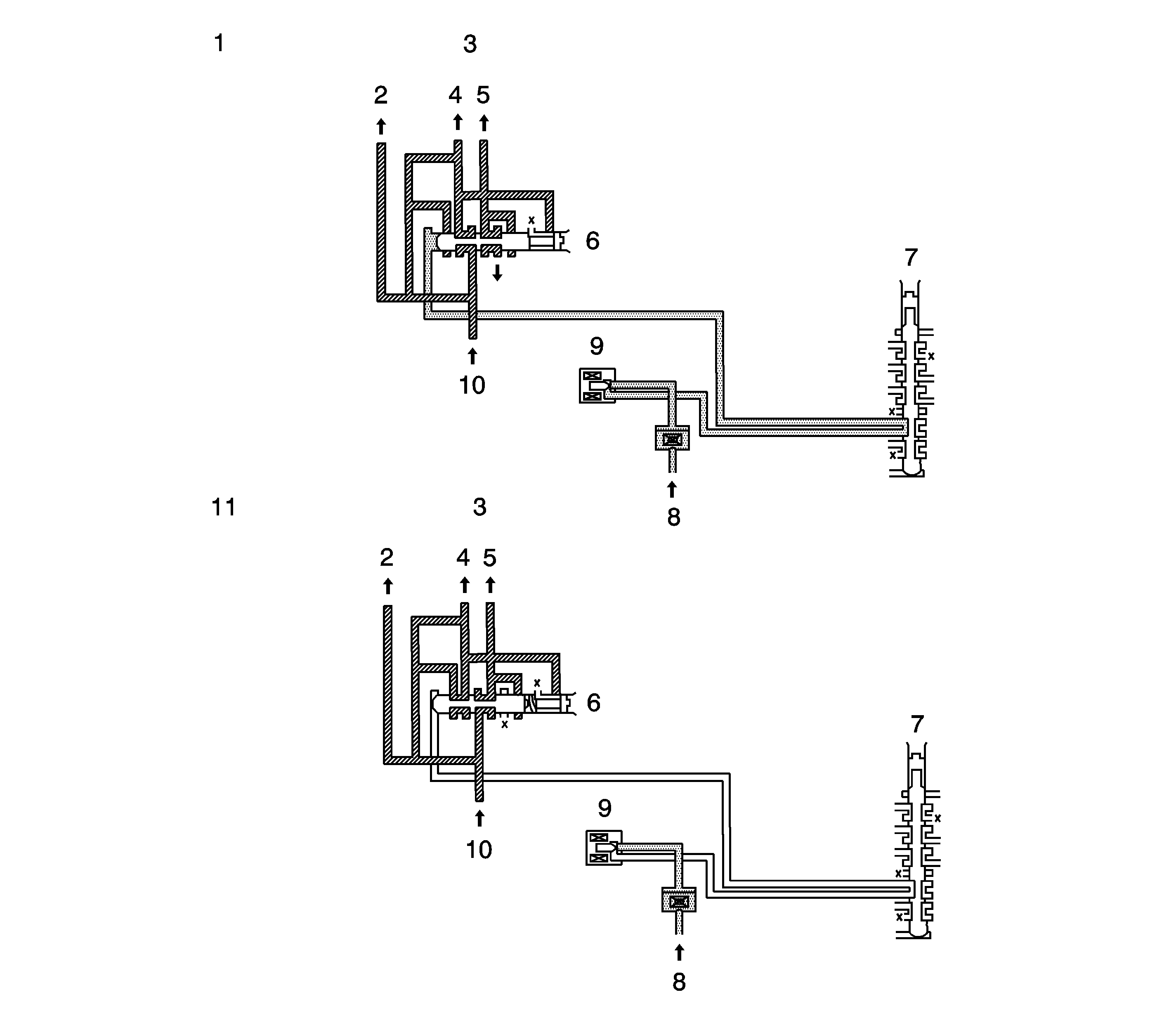

Object Number: 1282568  Size: LF
(1)Lock-up applied
(2)Lubricates inside transmission
(3)Lock-up clutch
(4)Engagement side
(5)Release side
(6)Lock-up control valve
(7)Shift valve B
(8)Pilot pressure
(9)Lock-up solenoid
(10)Line pressure
(11)Lock-up released

AT Controller

The AT controller is at the left side of the driver's footing. It sends an output signal to shift solenoids A and B, the line pressure solenoid and the lock-up solenoid in response to the input signal from each sensor to operate shift change in 1st, 2nd, 3rd, and 4th gears and lock-up control.

The AT controller is equipped with a diagnostic function to detect errors in the controller itself and the input signal.

If an error occurs, the fail-safe function works to secure a minimum driving performance.

Input Signals


Object Number: 1348457  Size: SH

The signals shown in the diagram specify the input signals for the AT controller (2) terminal.

Vehicle Speed Signal

The frequency fluctuation output from the vehicle speed sensor (1) is monitored and is input as vehicle speed.

The vehicle speed and throttle signals are used as data for shifting gear.

Oil Temperature Signal


Object Number: 1348458  Size: SH

Resistance (1) variation of the oil temperature (2) sensor is monitored via the variation of voltage and is input as AT fluid temperature.

The oil temperature signal is used to determine the shift point.

Overdrive Signal


Object Number: 1348459  Size: SH

The overdrive signal is switched by the overdrive switch.

Shifting to overdrive is not possible when the switch is ON (2), and it is possible when the switch is OFF (3).

Input Shaft Speed Signal


Object Number: 1348460  Size: SH

The input shaft speed signal is detected by the turbine sensor.

It is input as input shaft rotation and it is used as data for lock-up control.

Specification
1 period = 1 1/2 rev. (1)

Shift Position Signal


Object Number: 1348462  Size: SH

The present positions of the selector lever and the manual valve are detected by the output signal from the shift lever switch.

The shift position signal is used to determine the appropriate driving gear for the vehicle speed.

    • High (battery voltage) (1)
    • Selected terminal voltage (2)
    • Other terminal voltage (3)
    • Low (approx. 0V) (4)

Engine Speed Signal


Object Number: 1348463  Size: SH

The engine speed signal is input to the engine controller.

It is used as data for lock-up control

Specification
1 period = 2/3 rev. (1)

The Throttle Position Signal


Object Number: 1348464  Size: SH

Throttle position signal input to the engine controller is converted to duty signal and is input tot he AT controller. As the throttle opening angle increases, the "Low" time ratio increases.

Specification
Duty ratio = T1/T (1)

Air Conditioner Signal


Object Number: 1348466  Size: SH

The control signal from the engine controller to the air conditioner clutch relay is also sent to the AT controller.

While the air conditioner clutch is operating; that is, the air conditioner signal is "Low (approx. 0V)", the line pressure solenoid is controlled base on this signal.

    • High (battery voltage) (1)
    • Air conditioning OFF (2)
    • Air conditioning ON (3)
    • Low approx. 0V (4)

Output Signals


Object Number: 1348467  Size: SH

Output signals from the AT controller are examined by each input signal and then they are output.

Shift Solenoid A, B Signal

These signals operate shift solenoids A and B respectively.

1st gear

2nd gear

3rd gear

4th gear

Shift solenoid A

ON (2)

OFF (3)

OFF (3)

ON (2)

Shift solenoid B

ON (2)

ON (3)

OFF (3)

OFF (2)

Line Pressure Solenoid Signal


Object Number: 1348468  Size: SH

This signal is the duty signal that operates the line pressure solenoid to regulate the line pressure in response to the driving conditions.

It regulates throttle pressure applied to the pressure modifier valve.

    • Valve opening angle (1)
    • Duty OFF-time ratio (2)

Lock-Up Solenoid Signal

This signal operates the lock-up solenoid to execute the lock-up control.

The duty signal is output when lock-up is applied.

Sensors And Switches

Throttle Sensor

A throttle sensor is installed on the throttler shaft It detects the throttle position. The throttle position is converted to the throttle signal by the engine controller, and is output to the AT controller.

Shift Switch


Object Number: 1348469  Size: SH

A shift switch is installed on the manual shift shaft. The shift switch applies the battery voltage to the AT controller in response to the select lever position. The controller detects the positions of the select lever and the manual valve using the output voltage from the shift switch. It also works as a starter inhibit switch.

Vehicle Speed Sensor


Object Number: 1348470  Size: SH

A vehicle speed sensor is installed in the AT case. It detects the number of signal rotor teeth in the differential gear.

O/D Switch

An O/D switch is installed on the select lever. It determines whether shifting to overdrive (4th gear) is possible or not. Shifting to 4th gear is not possible when the switch is ON. When the vehicle is driving in 4th gear, the gear is shifted down to 3rd gear. Also, the O/D OFF indicator in the speedometer is lit to indicate that shifting up to 4th gear is not permitted.

Oil Temperature Sensor


Object Number: 1348471  Size: SH

The oil temperature sensor detects the AT fluid temperature. It is installed in the valve body.

Turbine Sensor


Object Number: 1348501  Size: MH

The turbine sensor (1) detects the input shaft rotation speed. It is installed on the mounting (side cover) at the side of the transmission case.