For 1990-2009 cars only
Tools Required
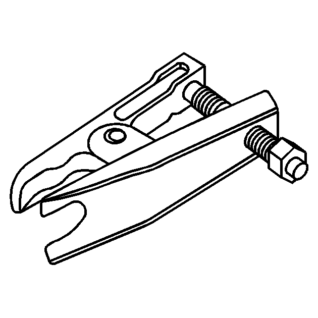
KM-507-C Ball Joint Remover
Removal Procedure
- Raise and support the vehicle on a wheel alignment rack. Refer to Lifting and Jacking the Vehicle.
- Remove the tire and wheel assembly. Refer to Tire and Wheel Removal and Installation.
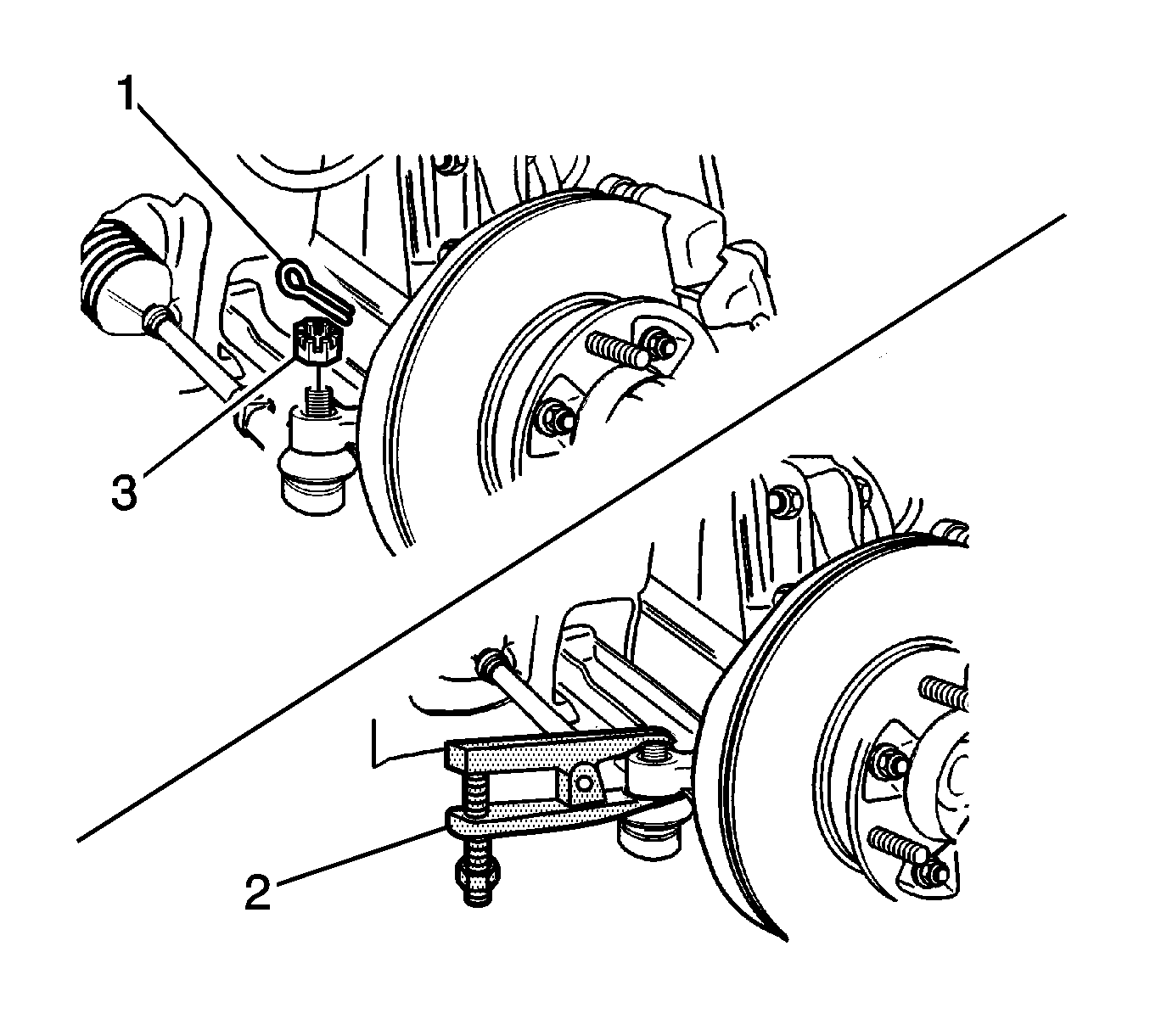
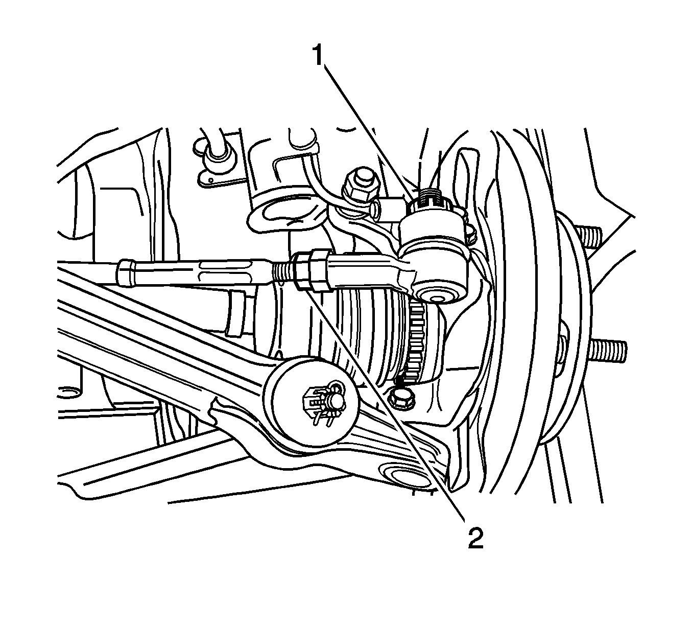
- Remove the cotter pin (1).
- Remove the tie rod end-to-steering knuckle nut (3).
- Use the KM-507-C (2) in order to disconnect the outer tie rod end from the steering knuckle.
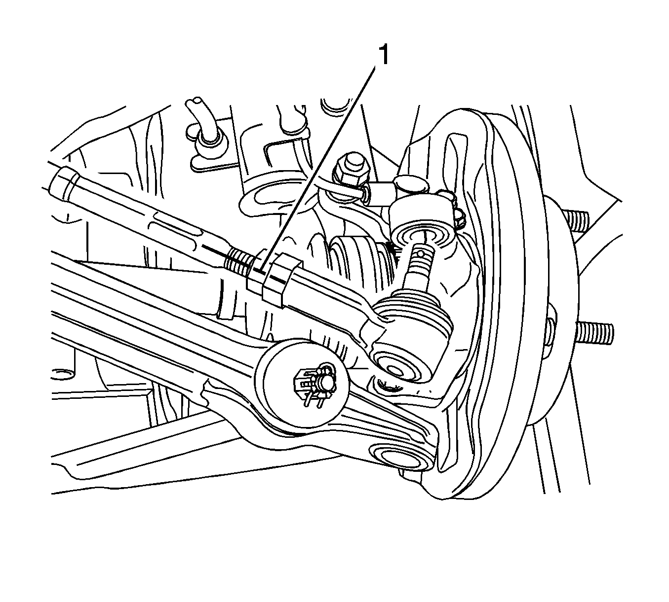
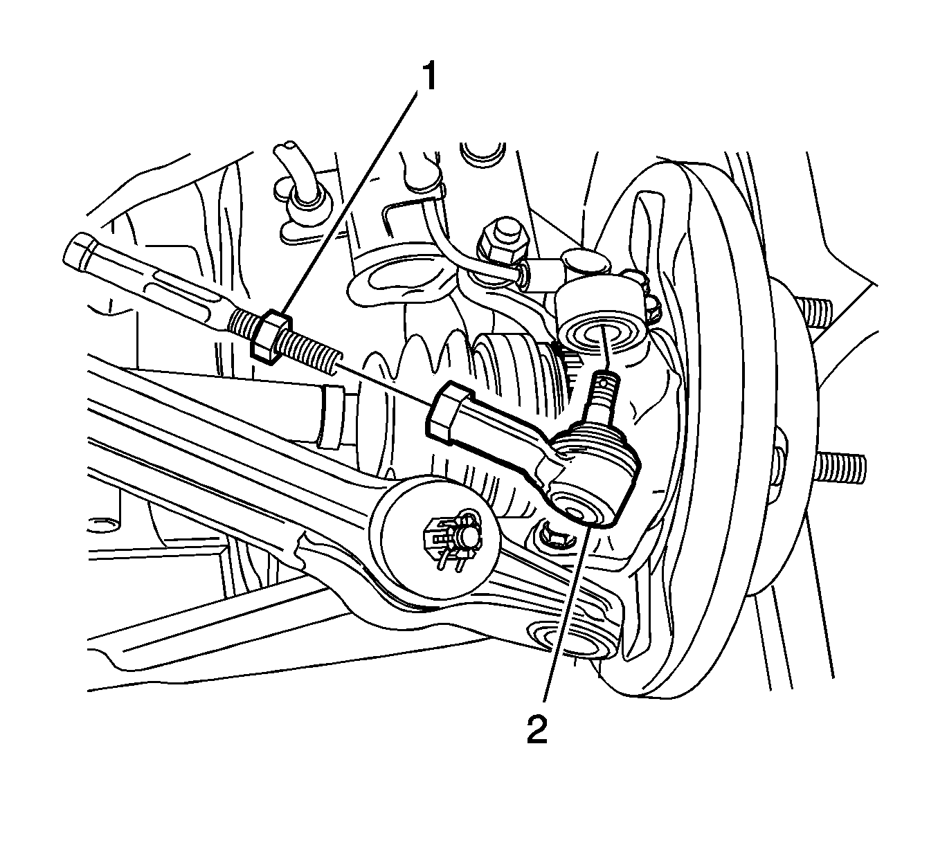
- Mark (1) the inner tie rod, the lock nut, and the outer tie rod end in order to aid in repositioning the lock nut.
- Loosen the lock nut (1).
- Remove the outer tie rod end (2).
Installation Procedure
- Reposition the lock nut (2) to the marks on the inner tie rod.
- Install the outer tie rod end to the inner tie rod.
- Connect the outer tie rod end to the steering knuckle.
- Install the tie rod end-to-steering knuckle nut (1).
- Install the cotter pin.
- Install the tire and wheel assembly. Refer to Tire and Wheel Removal and Installation.
- Measure the wheel alignment. Adjust the front toe if necessary. Refer to Front Toe Adjustment.
- Tighten the lock nut.
- Lower the vehicle.
Notice: Refer to Fastener Notice in the Preface section.
Tighten
Tighten the tie rod end-to-steering knuckle nut to 45 N·m (33 lb ft).
Tighten
Tighten the lock nut to 45 N·m (33 lb ft).
