Overdrive Overhaul Planetary Gear Side
Tools Required
| • | J 41681 Clutch Spring Compressor |
| • | J 8001 Dial Indicator Set |
| • | J 36850 Transjel® Transmission Assembly Lubricant |
Removal Procedure
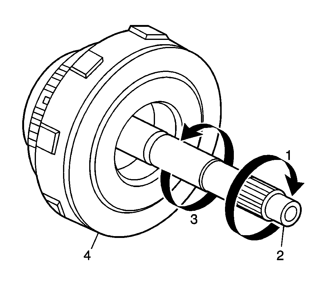
- Hold the overdrive clutch drum (4) in a stationary position.
- Confirm that the input shaft (2) turns smoothly in the clockwise direction (1).
- Confirm that the input shaft locks in the counter clockwise direction (3).
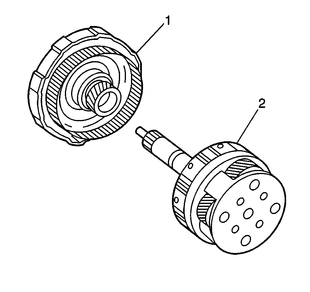
- Remove the overdrive planetary gear (2) from the overdrive clutch drum (1).
- Perform the following steps in order to measure the overdrive clutch piston stroke:
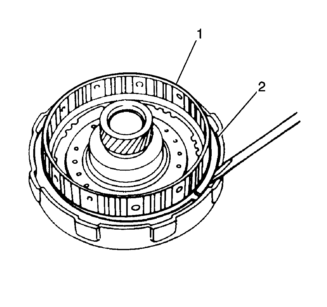
- Remove one brake hub snap ring (2) from the overdrive clutch drum.
- Remove the brake hub (1) from the overdrive clutch drum.
- Remove the cushion plate snap ring (1).
- Remove the following components from the overdrive clutch drum (2):
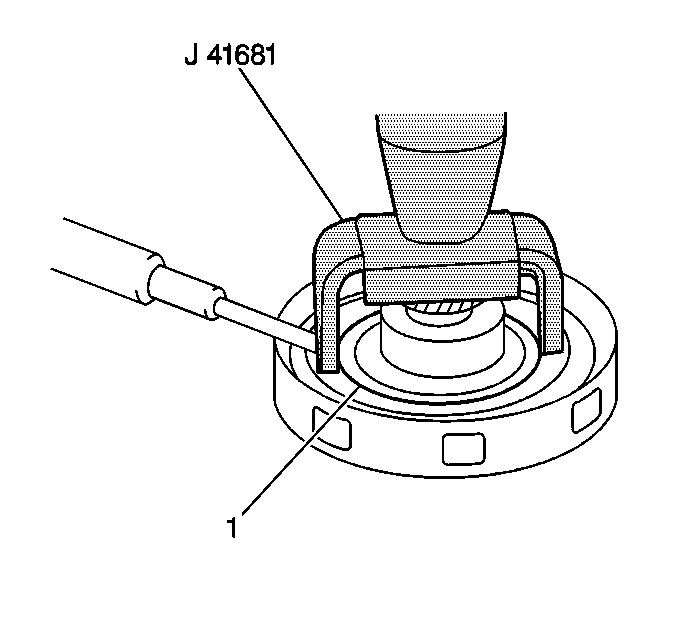
- Compress the overdrive clutch piston (1) using J 41681 while removing the snap ring.
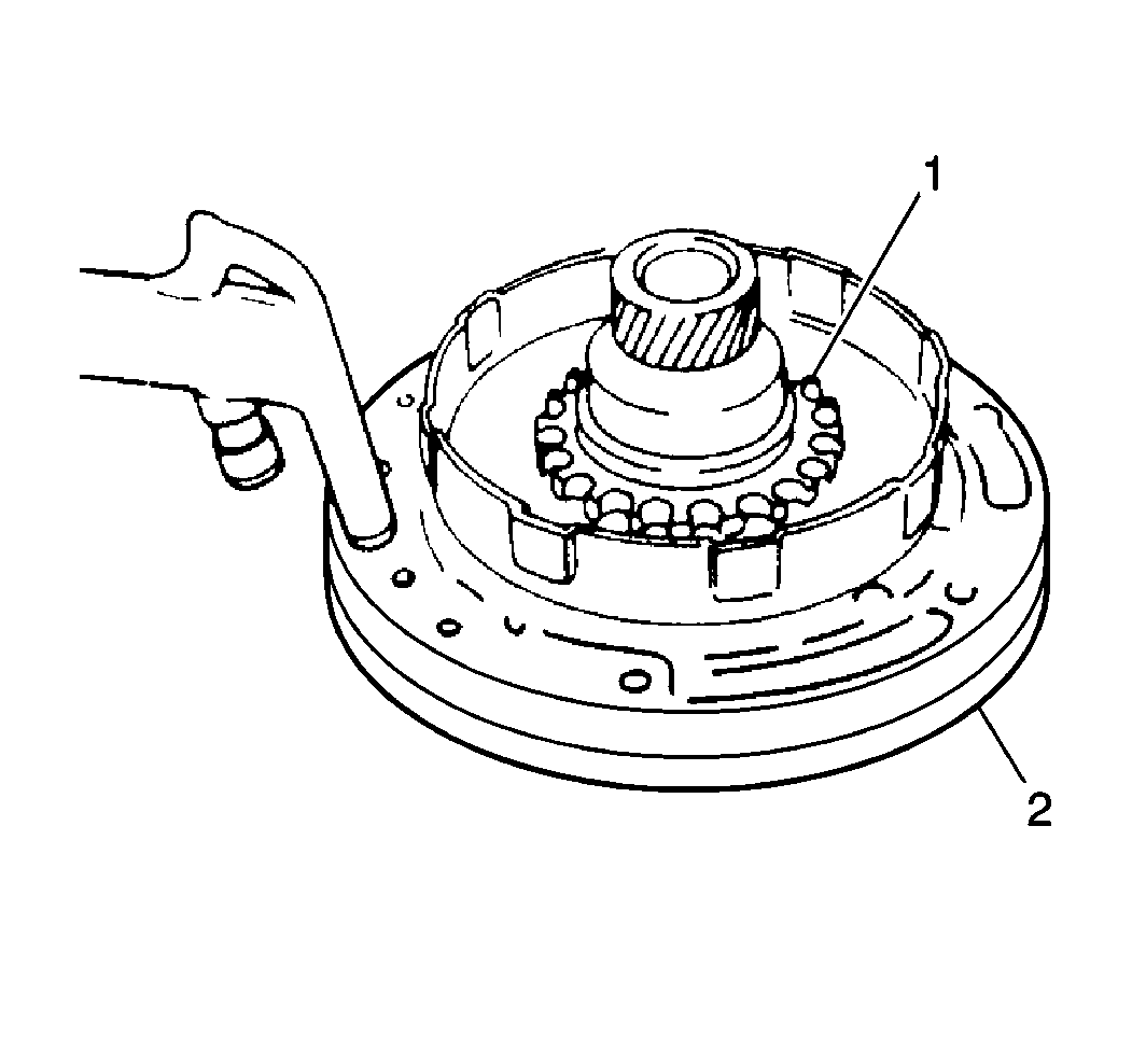
- Temporarily install the overdrive clutch drum to the oil pump (2).
- Apply compressed air into the oil passage.
- Remove the overdrive clutch drum from the oil pump.
- Remove the inner and outer O-rings from the overdrive clutch piston.
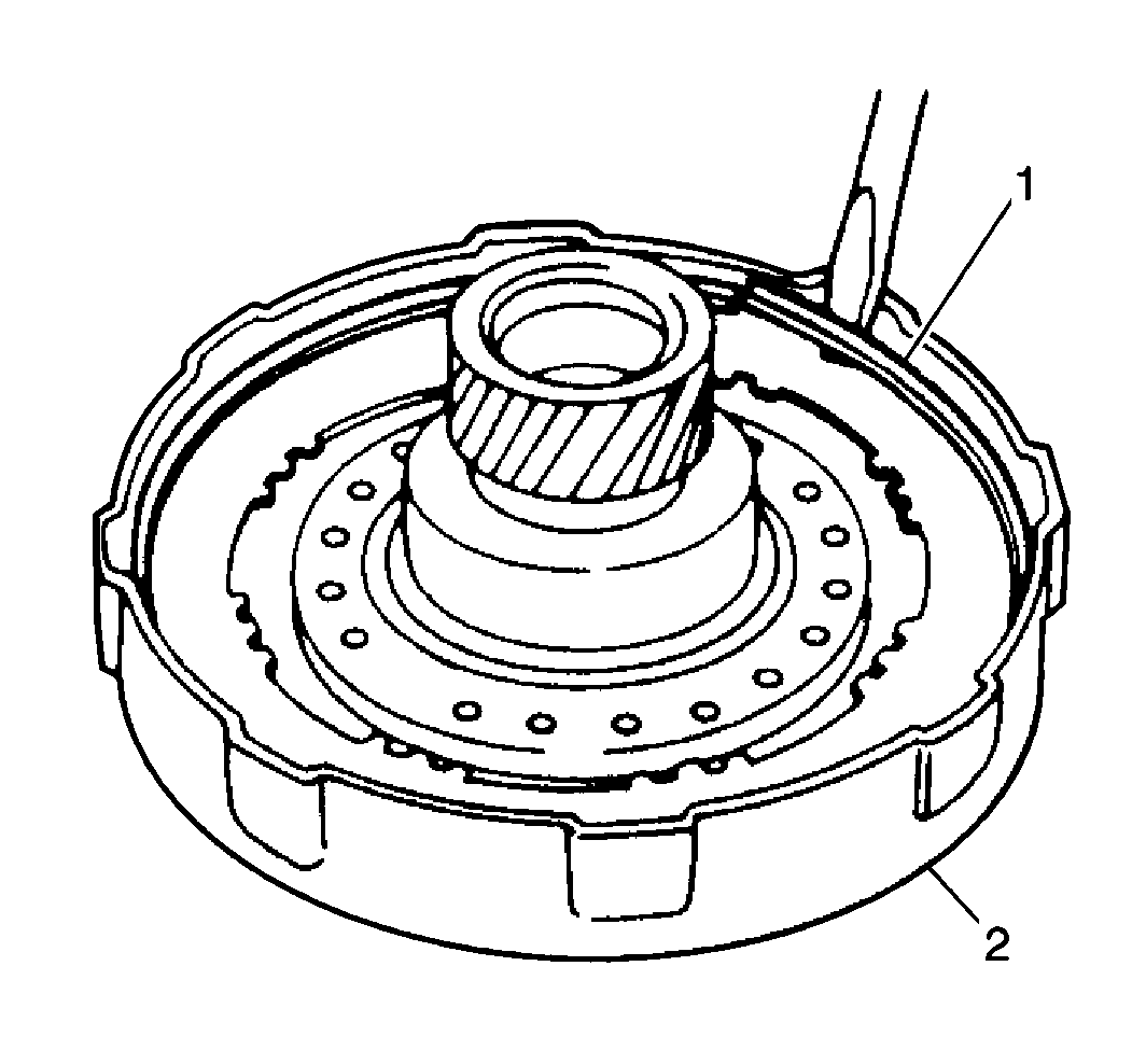
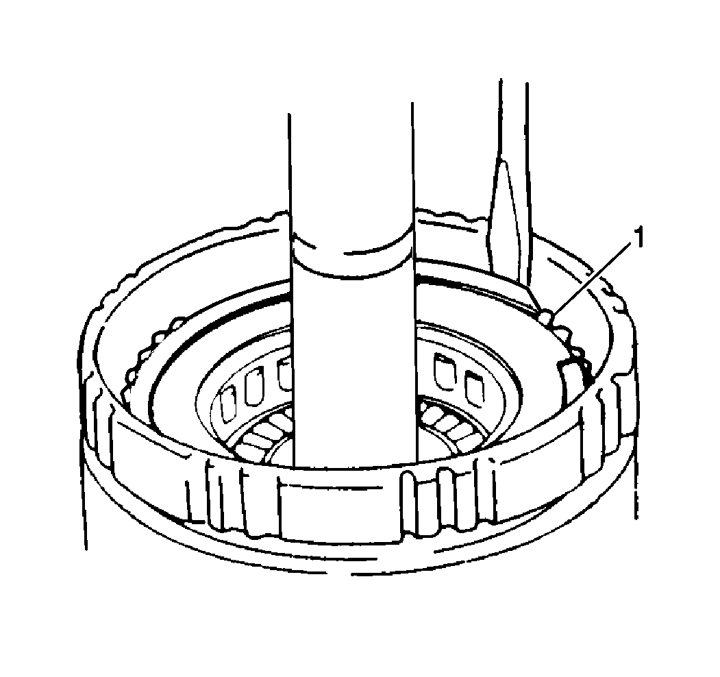
- Remove the overdrive planetary gear snap ring using a flathead screwdriver.
- Remove the following components from the overdrive planetary gear (1):
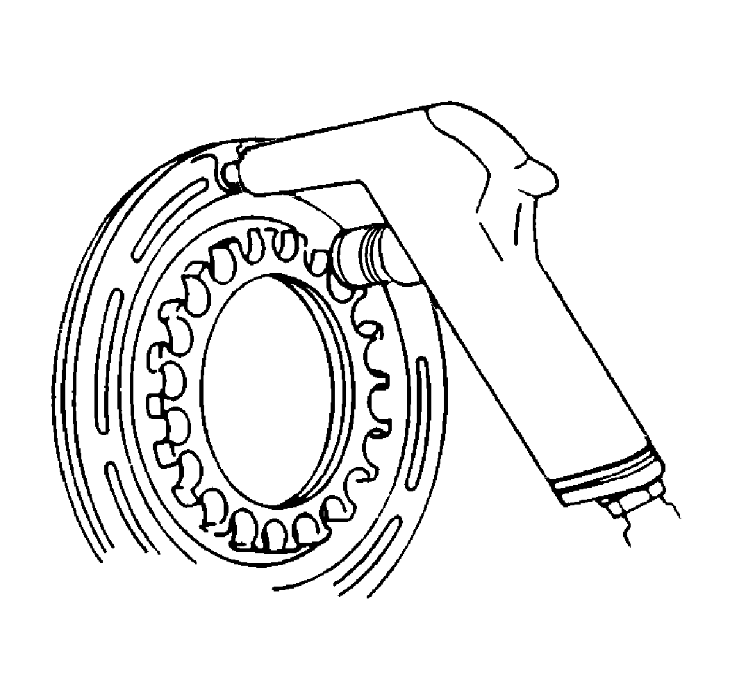
- Clean all overdrive clutch components.
- Allow the components to air dry.
- Inspect the overdrive clutch disc for excessive wear or damage. Replace as necessary.
- Inspect the overdrive clutch piston porosity. Replace as necessary.
- Shake the clutch piston in order to make sure that the check ball moves freely.
- Apply low air pressure to the overdrive clutch piston check ball opening in order to inspect for leaks.
- Inspect the one-way clutch flange. Replace as necessary.
- Inspect the planetary thrust washer. Replace as necessary.
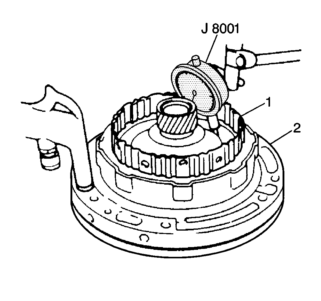
| 5.1. | Temporarily install the overdrive clutch drum (1) to the oil pump (2). |
| 5.2. | Place the J 8001 plunger on the overdrive clutch piston. |
| 5.3. | Apply 392-785 kPa (57-114 psi) of compressed air into the oil passage. |
| 5.4. | Measure the movement of the overdrive clutch piston. |
Specification
Overdrive clutch piston stroke (standard): 1.47-2.28 mm
(0.058-0.089 in)
| 5.5. | Replace the following components as needed if the stroke is not within specifications: |
| • | The cushion clutch plate |
| • | The clutch disc |
| • | The cushion plate |
| • | The backing plate |
| • | The clutch disc |
Important: When removing the components using compressed air, the air pressure should not exceed 98 kPa (14 psi).
| • | The one-way clutch |
| • | The thrust washer |
| • | The thrust bearing |
Installation Procedure
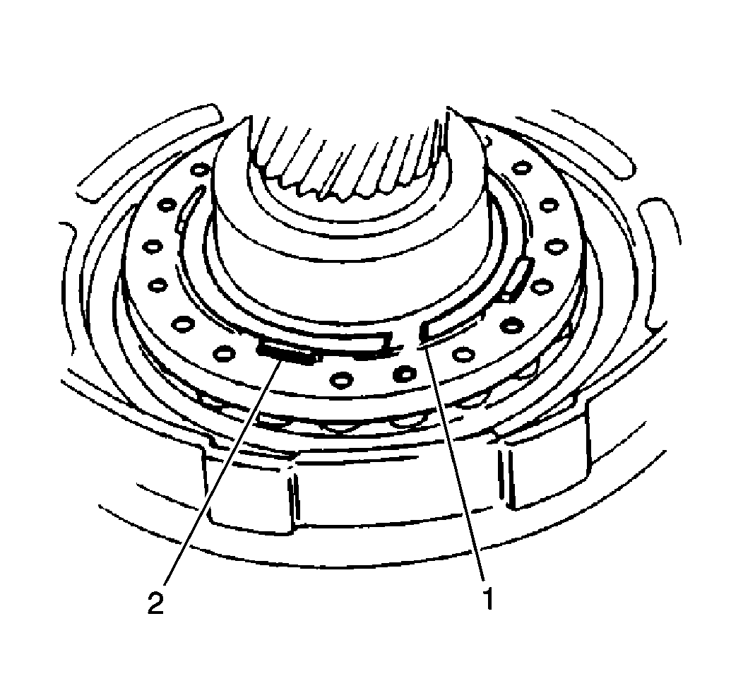
Important: When installing the one-way clutch snap ring, do not align the snap ring opening with the lug on the clutch piston spring retainer.
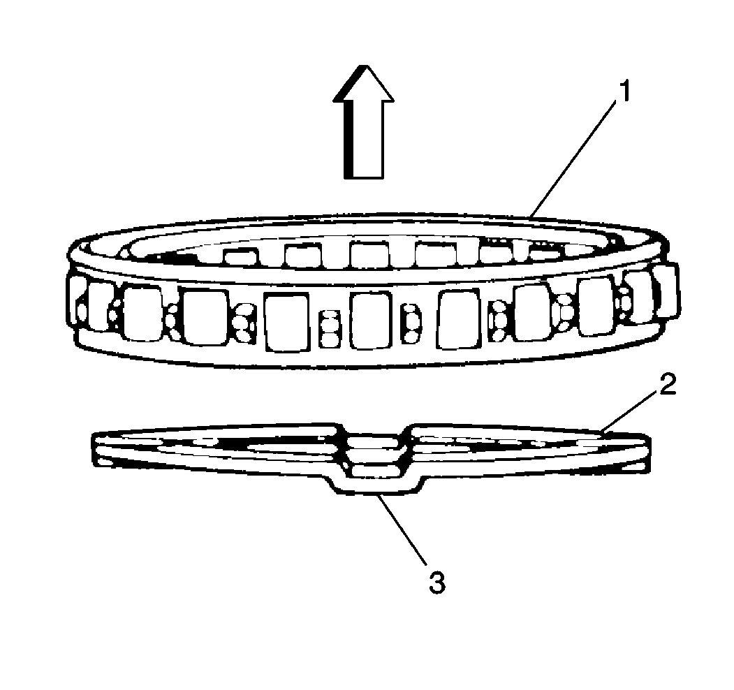
- Install the planetary thrust washer (2) with the oil groove (3) facing the front.
- Install the one-way clutch outer bearing race with the flange (1) facing the front.
- Apply J 36850 to the following components:
- Install the thrust bearing and the planetary thrust washer into the overdrive planetary gear.
- Install the one-way clutch to the overdrive planetary gear.
- Install the overdrive planetary gear snap ring (1) .
- Install new O-rings to the inner and outer overdrive clutch pistons.
- Lubricate the O-rings with A/T fluid.
- Install the overdrive clutch piston to the overdrive clutch drum.
- Install the overdrive clutch piston return springs (2) .
- Compress the overdrive clutch piston (1) using J 41681 while installing the overdrive clutch piston snap ring.
- Install the following components to the overdrive clutch drum:
- Install the brake hub snap ring (2).
| • | The thrust bearing |
| • | The planetary thrust washer |

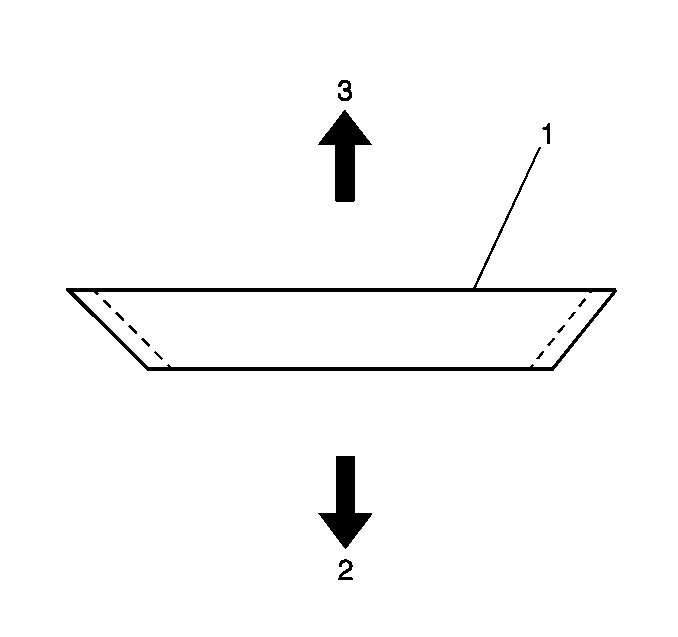
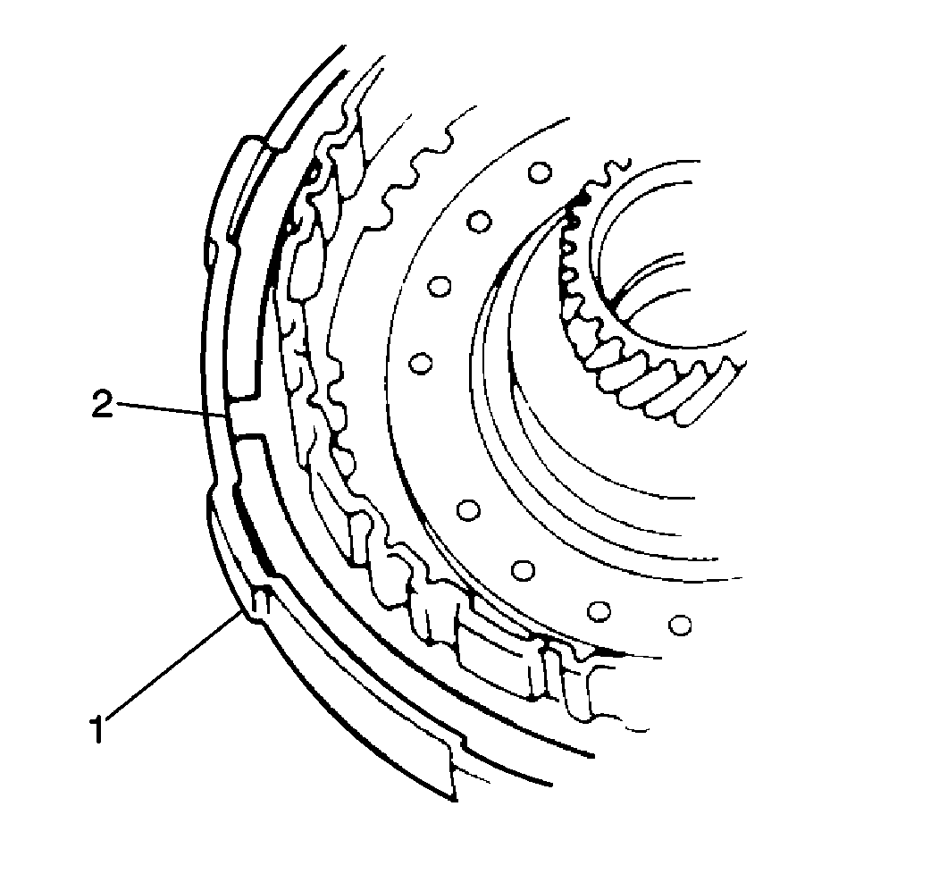
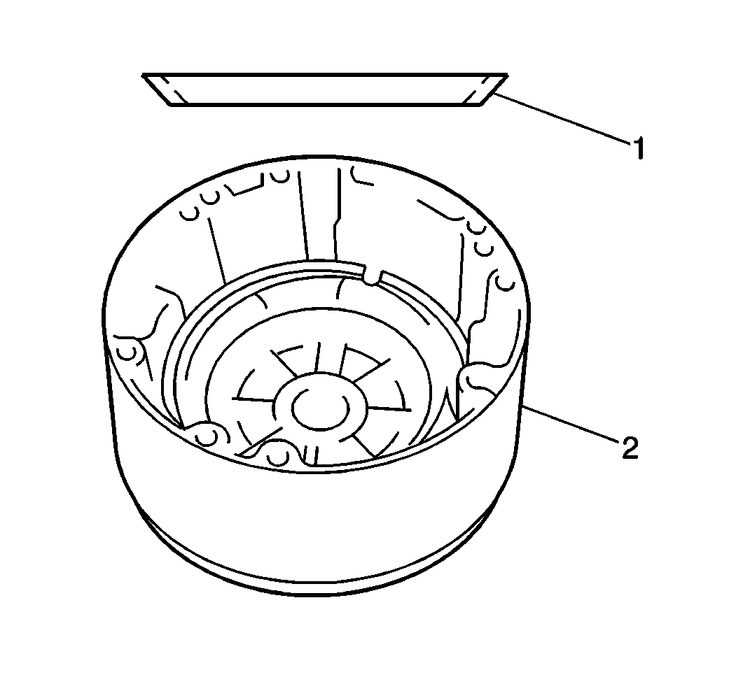
Important: Refer to the graphic when installing the cushion plate.
| • | The clutch disc |
| • | The backing plate |
| • | The cushion plate (1) |
| • | The snap ring |
| • | The brake hub |
Overdrive Overhaul Case Side
Tools Required
| • | J 26900-5 Vernier Caliper |
| • | J 36850 Transjel® Transmission Assembly Lubricant |
Removal and Inspection Procedure
- Place the feeler gage between the brake flange (2) and the snap ring (1) in order to measure the clearance.
- Measure the clearance.
- Replace the clutch disc or plate if the readings are not as specified.
- Remove the following components from the overdrive case:
- Remove the following clutch piston return spring components using a flathead screwdriver:
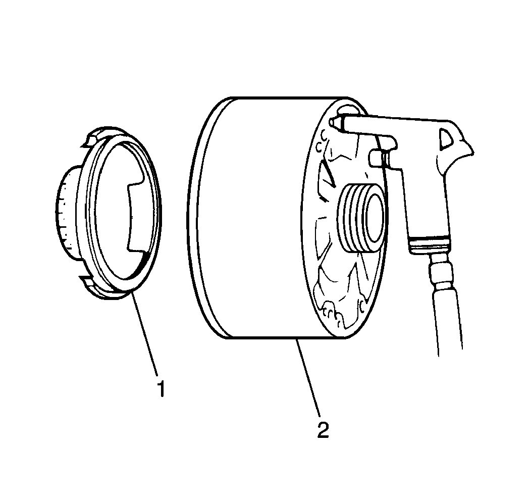
- Apply low compressed air into the overdrive case (2) fluid hole in order to remove the brake piston (1).
- Remove the brake piston O-rings.
- Remove the following components from the rear of the overdrive case.
- Measure the free length of the clutch piston return springs (1) using J 26900-5 .
Specification
Brake flange-to-snap ring clearance (standard): 0.35-1.91 mm
(0.014-0.075 in)
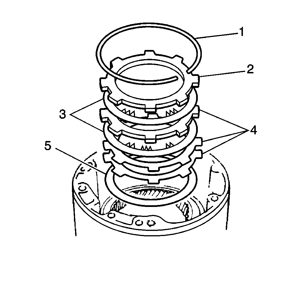
| • | The brake flange snap ring (1) |
| • | The brake flange (2) |
| • | The clutch discs (3) |
| • | The clutch plates (4) |
| • | The cushion brake plate (5) |
| • | The planetary ring gear |
| • | The thrust bearing races |
| • | The thrust bearing |
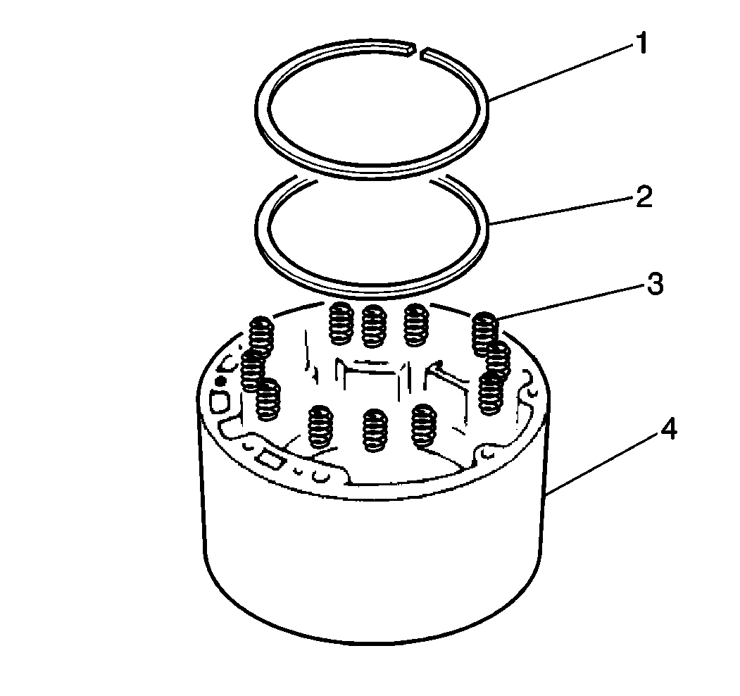
| • | The snap ring (1) |
| • | The retainer (2) |
| • | The springs (3) |
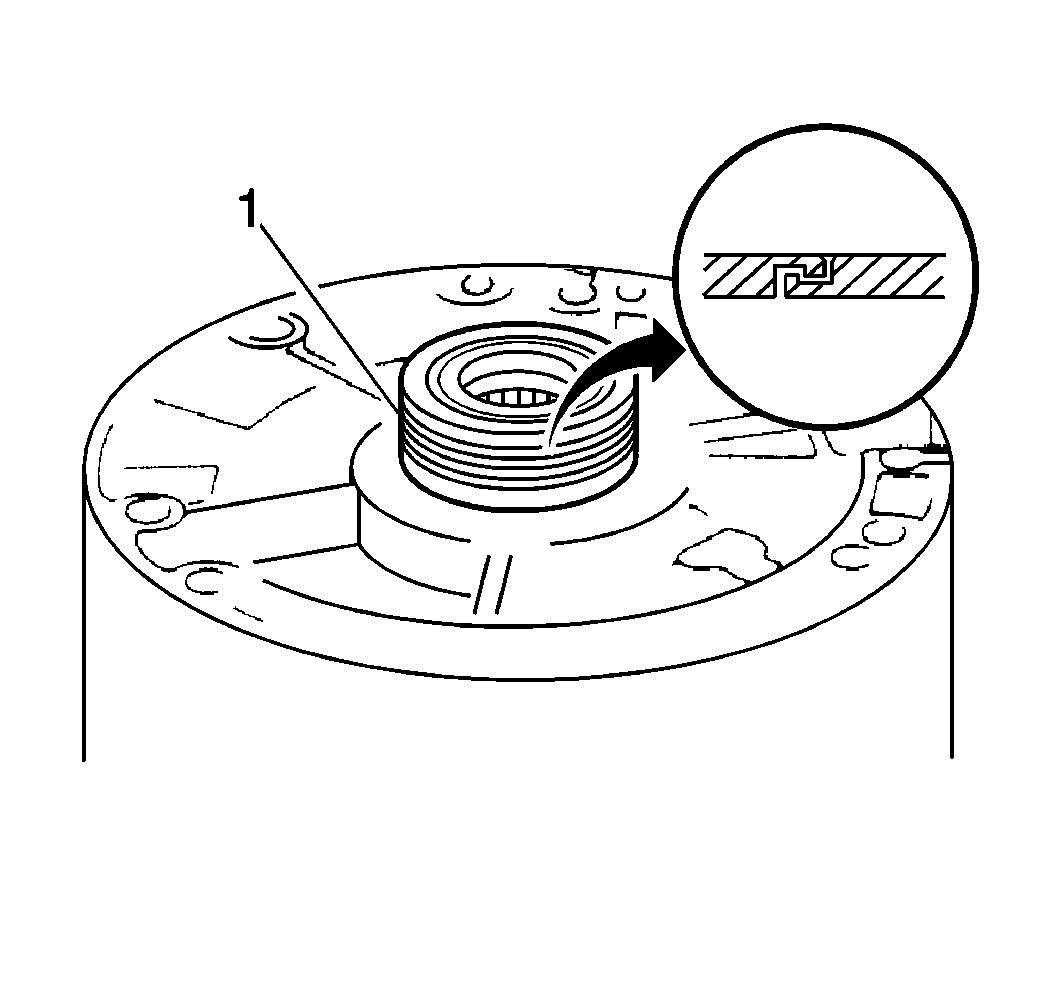
| • | The 2 sealing rings (1) |
| • | The bearing |
| • | The bearing race |
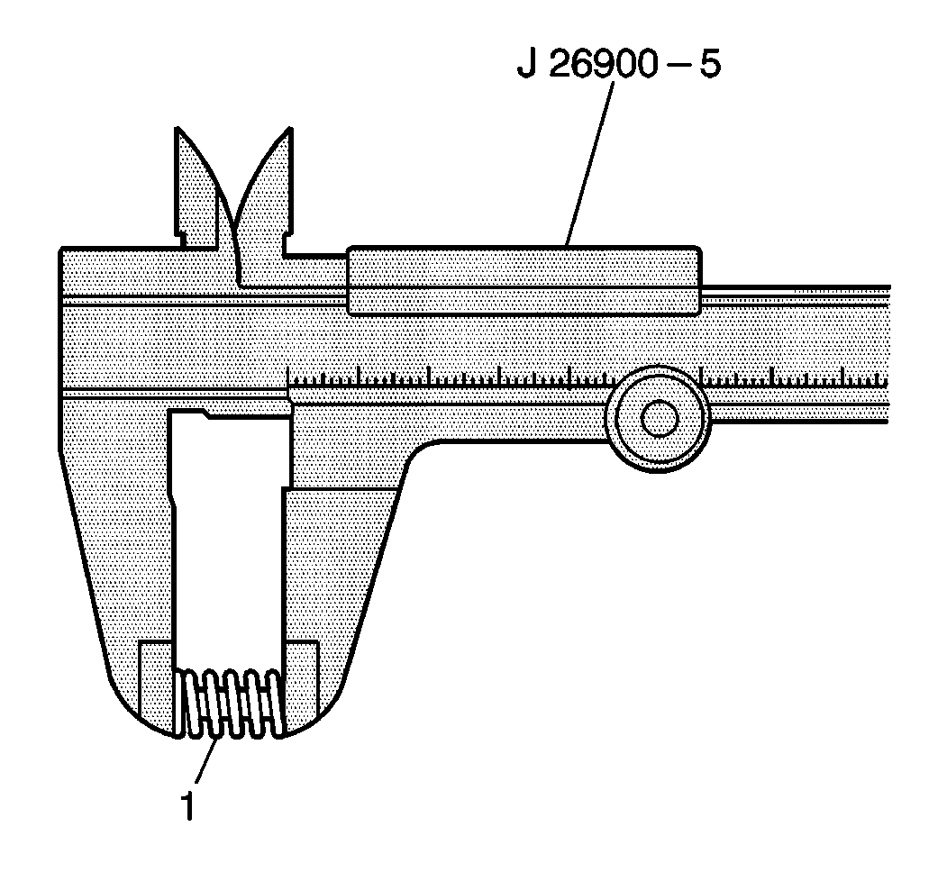
Specification
Clutch piston return spring free length (standard): 15.10 mm
(0.594 in)
Replace the springs which are not within specifications.
Installation Procedure
- Apply J 36850 to the bearing and race.
- Install the bearing and race to the rear of the overdrive case.
- Install new seal rings to the rear of the overdrive case.
- Lubricate the seals with A/T fluid.
- Install the brake piston.
- Install the following components into the overdrive case:
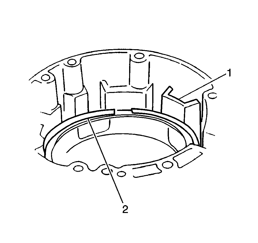
- Inspect that the snap ring end gap does not align with one of the overdrive case cutouts.
- Install the following components in the exact order given to the overdrive case after applying J 36850 :
- Install the planetary ring gear.
- Install the cushion brake plate.
- Install the overdrive clutch plates (1) and discs in the following order:
- Install the brake plate.
- Install the brake plate snap ring, making sure the end gap does not align with any of the overdrive case cutouts.
- Measure the brake backing plate-to-snap ring clearance using a feeler gage.
| • | The 20 piston return springs |
| • | The piston spring retainer |
| • | The snap ring (2) |
| 8.1. | The bearing race |
| 8.2. | The thrust bearing |
| 8.3. | The thrust bearing race |
| 11.1. | The plate |
| 11.2. | The plate |
| 11.3. | The disc |
| 11.4. | The plate |
| 11.5. | The disc |
Specification
Brake backing plate-to-snap ring clearance (standard): 0.35-1.91 mm
(0.014-0.075 in)
Disassemble and inspect if the clearance is not within specifications.
