SMU - Revised Body Mount Replacement - Front and Body Mount Replacement - Rear

| Subject: | Revised Body Mount Replacement - Front and Body Mount Replacement - Rear |
| Models: | 2003-2005 Chevrolet Kodiak Models |
| 2003-2005 GMC TopKick Models |
| 2005 Isuzu HTR/HVR/HXR Conventional Models |
This bulletin is being issued to revise the Body Mount Replacement-Front and the Body Mount Replacement-Rear procedures in the Frame and Underbody sub-section of the Service Manual. Please replace the current information in the Service Manual with the following information.
The following information has been updated within SI. If you are using a paper version of this Service Manual, please make a reference to this bulletin on the affected page.
Body Mount Replacement - Front
Notice: The cab must be properly supported and the weight of the cab evenly distributed during cab mount replacement. Failure to provide support could result in damage to the vehicle.
Ensure to support the cab properly while changing the mount. Tilt the hood and install lifting straps. Refer to Cab Replacement in Body Front End. If changing only one mount, remove the nut on the bottom of the other mount and the nuts beneath the rear support. Removing these nuts will allow the cab to be lifted enough to provide clearance. If lifting straps cannot be used, place jacks under the cab. Position one jack near the mount being replaced. Place another jack under one of the longitudinal sills running from the front to the rear of the cab under the floor. Place a strong block of wood at least 150 mm x 150 mm (6 in x 6 in) between the jack and the cab sill in order to distribute the weight of the cab.
Removal Procedure
- From underneath the cab, remove the nut and the washer from both of the front mounts.
- Remove the nut and the washer from beneath the rear support.
- Remove the 2 nuts and the washers.
- Remove the front floor mat.
- Remove the inner rocker panel plug from the floor at the mount to be replaced.
- Remove the front cab mounting bolt from the floor.
- Remove the 2 bolts and nuts that secure the cab mount assembly to the frame rail bracket.
- Remove the mount assembly and the retainers from the frame rail bracket on the frame rail.
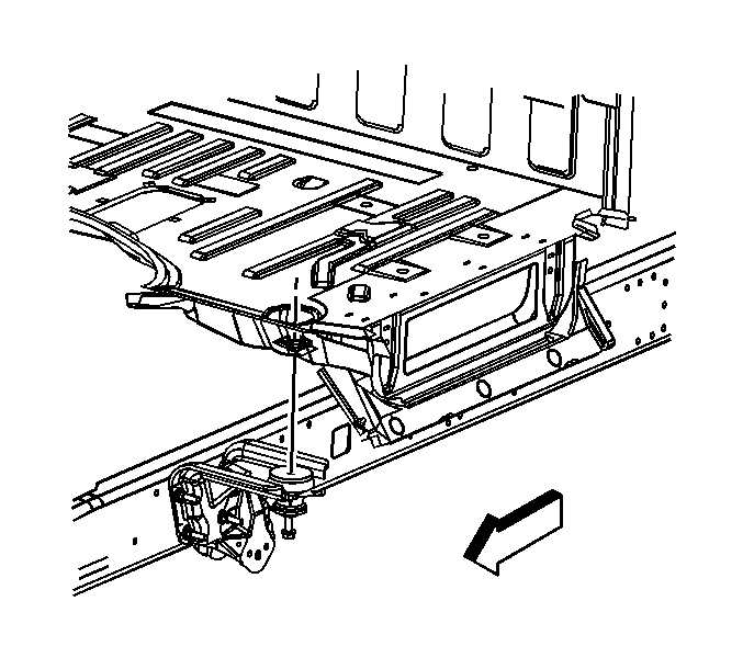
Raise the cab enough to permit removal of the 2 cab mount to frame bracket bolts.
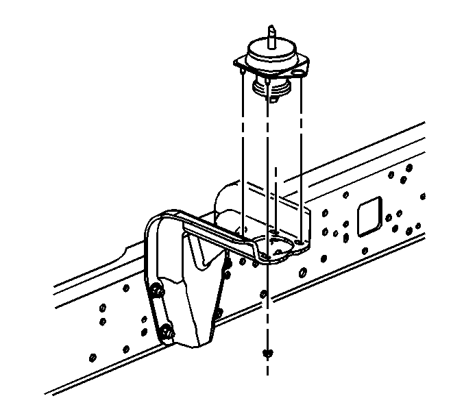
Installation Procedure
- Install the cab mount assembly and the retainers between the cab and the frame bracket.
- Install the 2 short bolts, the washers, the spacers, and the nuts through the cab mount and the mounting bracket.
- Install the cab mounting bolt through the plate, the floor, the mount assembly, and the frame bracket.
- Install the mounting bolt washer and nut to the bottom of the cab mounting bolt.
- Lower the cab.
- Install the inner rocker panel plug to the floor.
- Install the floor mat.


Notice: Refer to Fastener Notice in Cautions and Notices.
Tighten
| • | Tighten the cab mount to cab bolts/nuts to 185 N·m (136 lb ft). |
| • | Tighten the cab mount assembly to frame bracket bolts to 100 N·m (74 lb ft). |
Body Mount Replacement - Rear
Removal Procedure
- Disengage the wiring harness connector retainer from the rear of the upper cab mount.
- Support the back of the cab.
- Remove the support bracket/cab mount assembly to the frame crossmember bolts.
- Raise the back of the cab slightly.
- Remove the support brackets/cab mount bolts.
- Remove the support brackets/cab mount assembly.
- Remove the mount to the cab support bracket bolts.
- Remove the mount from the cab support.
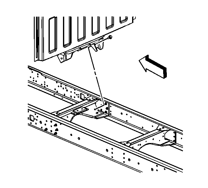
Important: Install lift straps or place a jack at each end of the rear cab sill. If jacks are used, place blocks of wood between the jacks and the sill.
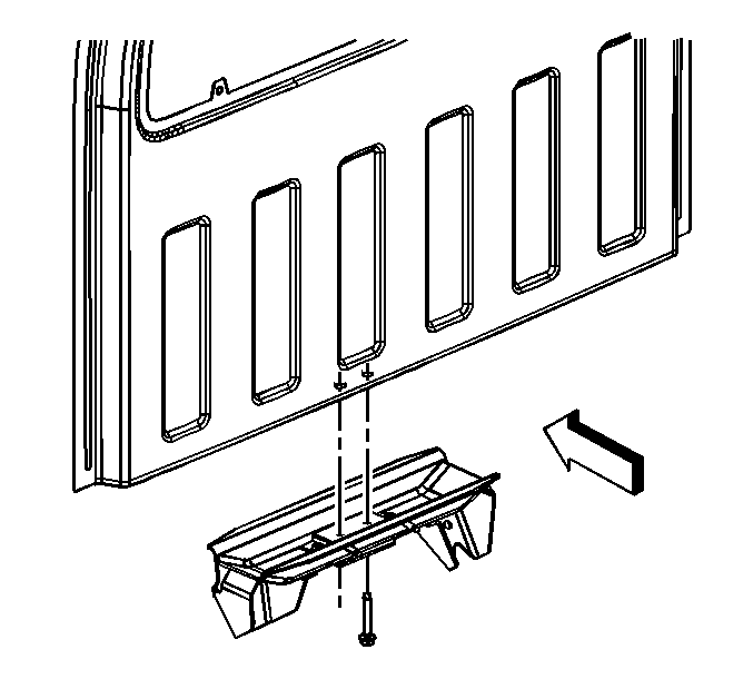
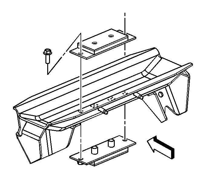
Installation Procedure
- Install the mount to the cab support bracket.
- Install the outboard bolts.
- Install the support bracket/cab mount to the cab.
- Install the support brackets/cab mount bolts.
- Lower the back of the cab.
- Install the support bracket/cab mount assembly to the frame crossmember bolts.
- Engage the wiring harness connector retainer to the rear of the upper cab mount.

Important: Ensure that the word TOP on the mount is oriented properly.
Notice: Refer to Fastener Notice in Cautions and Notices.
Tighten
Tighten the cab mount to cab support bracket bolts to 85 N·m (63 lb ft).

Tighten
Tighten the support bracket/cab mount to the cab bolts to 185 N·m (251 lb ft).

Tighten
Tighten the support bracket/cab mount assembly to the frame crossmember bolts to 260 N·m (192 lb ft).
