Removal Procedure
Important: The intake manifold, throttle body, fuel rail, and injectors may be removed as an assembly. If not servicing the individual components, remove the manifold as a complete assembly.
- Remove the air cleaner layer. Refer to Air Cleaner Replacement .
- Remove the throttle body. Refer to Throttle Body Assembly Replacement .
- Remove the fuel rail. Refer to Fuel Injection Fuel Rail Assembly Replacement .
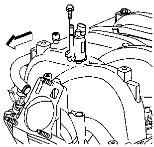
- Remove the purge solenoid bolt and purge solenoid.
- Inspect the purge solenoid seal for damage. Replace the seal as needed.
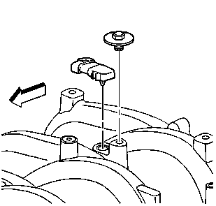
- Remove the manifold absolute pressure (MAP) sensor bolt and sensor.
- Inspect the MAP sensor seal for damage.
- Remove the oil fill tube. Refer to Oil Filler Tube Replacement .
- Remove the intake manifold bolts.
- Remove the intake manifold.
- Remove and discard the intake manifold side gaskets.
- Remove and discard the intake manifold end gaskets.
- Remove the intake manifold oil splash shield.
- Clean and inspect the intake manifold.
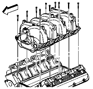
Important: Do not attempt to loosen the manifold by prying under the gasket surface with any tool.
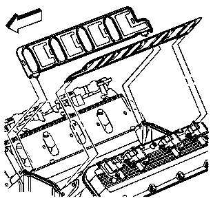
Important: The intake manifold gaskets are not reusable.
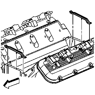
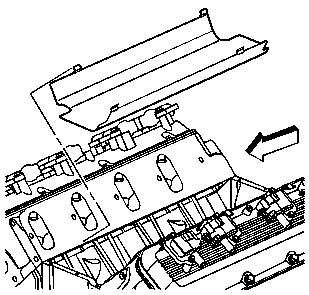
Important: The oil splash shield is secured using a snap-in fit. Do not distort the splash shield. The shield is reusable.
Installation Procedure
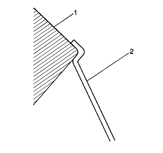
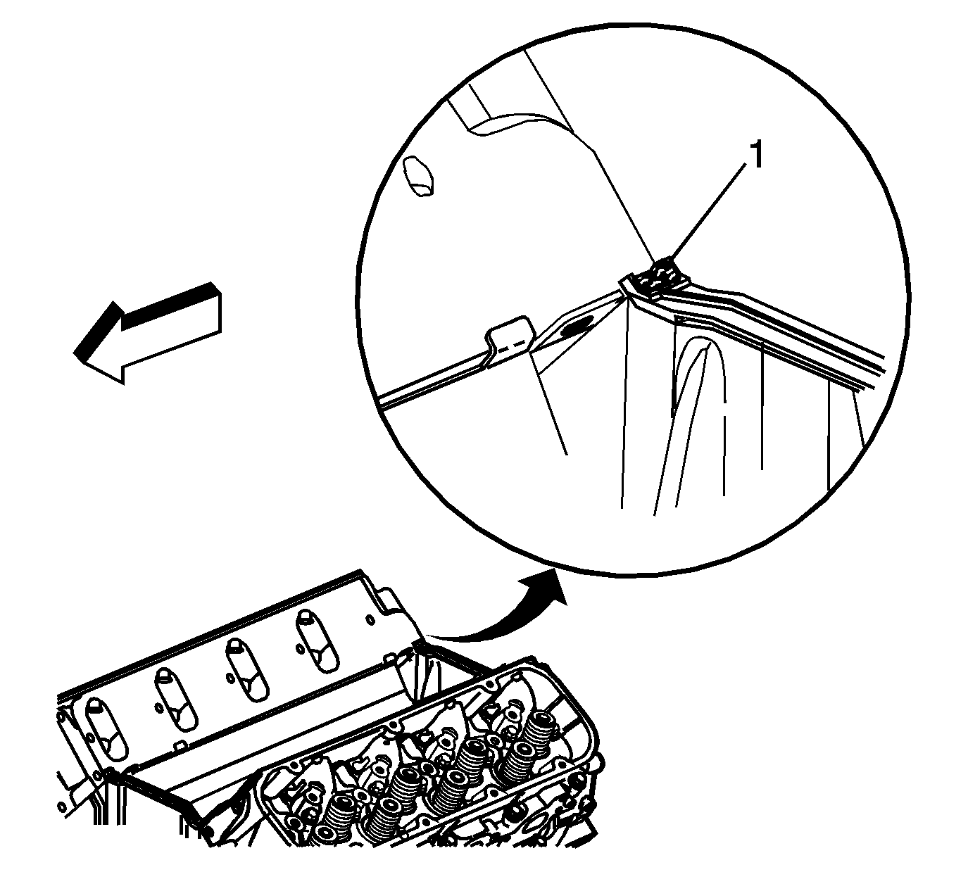
- Install the intake manifold oil splash shield.
- Ensure the splash shield (2) snap fits between the cylinder heads (1).
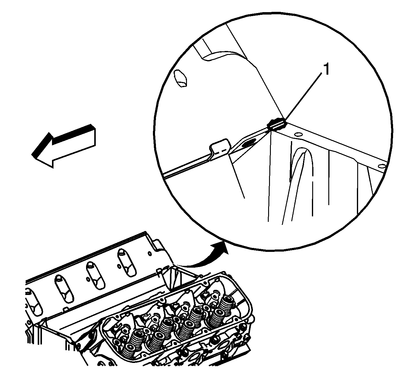
- Apply a 5 mm (0.2 in) bead of sealer (1) to the 4 engine block/cylinder head locations. Refer to Adhesives, Fluids, Lubricants, and Sealers for the correct part number.
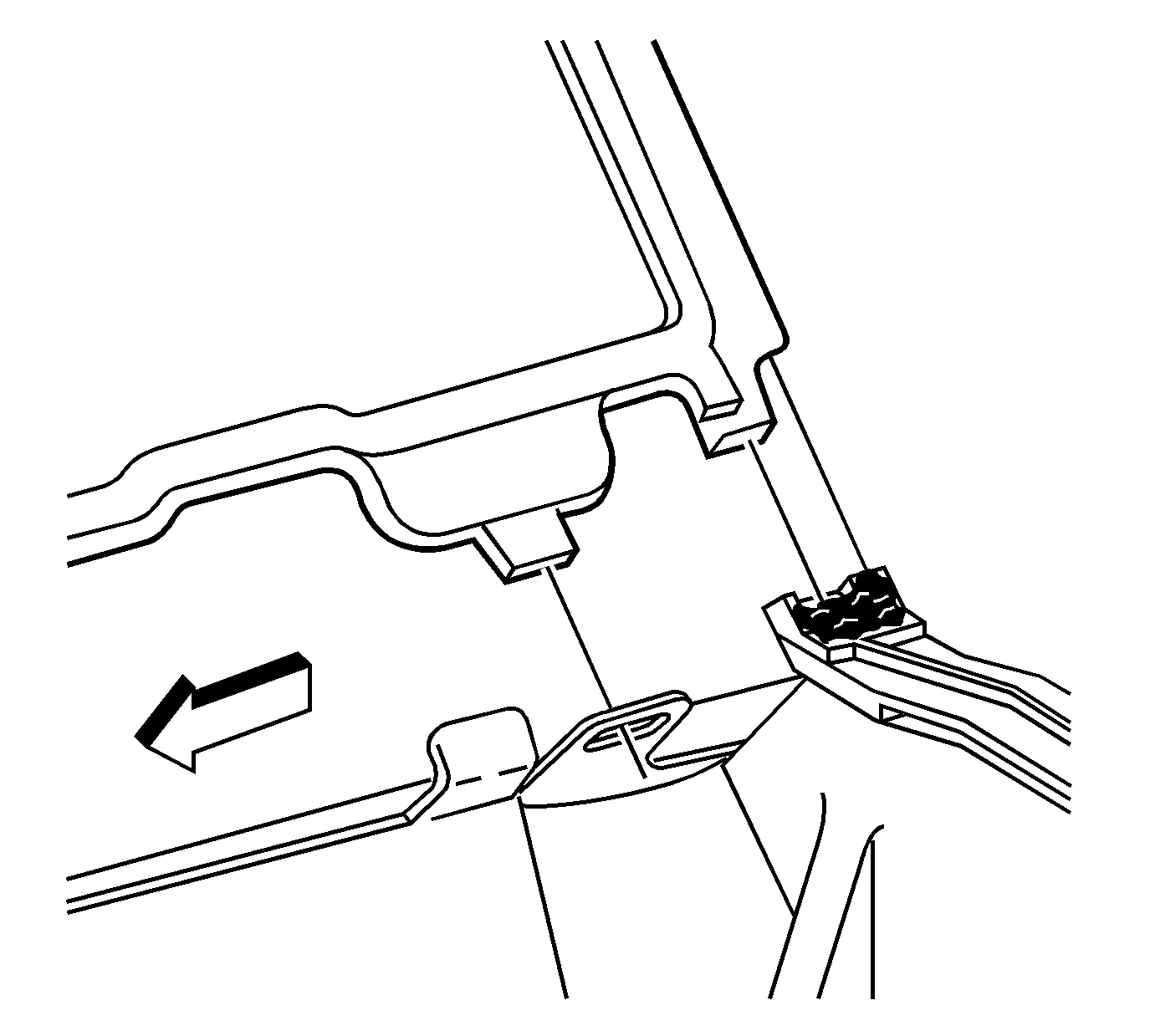
- Install the new intake manifold end gaskets.
- Apply a 5 mm (0.2 in) bead of sealer (1) onto the end seals at the 4 engine block/cylinder head locations. Refer to Adhesives, Fluids, Lubricants, and Sealers for the correct part number.
- Install the new intake manifold side gaskets.
- Ensure the intake manifold gasket tabs align with the hole in the head gasket.
- Ensure the intake manifold gasket tabs align with the slot in the intake manifold end gaskets.
- Install the intake manifold.
- Install the new intake manifold bolts.
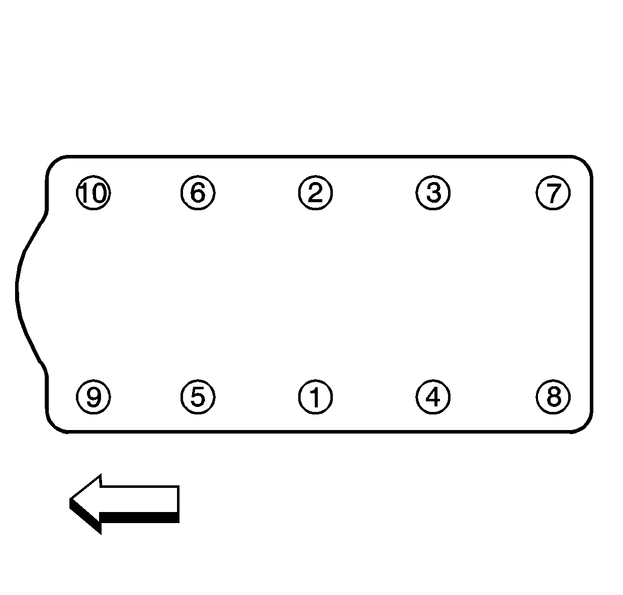
- Tighten the intake manifold bolts in sequence, using 4 passes.
- Tighten the intake manifold bolts in sequence to 5 N·m (44 lb in) on the first pass.
- Tighten the intake manifold bolts in sequence to 8 N·m (81 lb in) on the second pass. Inspect the intake manifold joints for signs of intake manifold shifting. Correct as required.
- Tighten the intake manifold bolts in sequence to 12 N·m (106 lb in) on the third pass.
- Tighten the intake manifold bolts in sequence to 15 N·m (11 lb ft) on the final pass.
- Install the oil fill tube. Refer to Oil Filler Tube Replacement .
- Install the MAP sensor.
- Install the MAP sensor bolt.
- Apply a very light film of clean engine oil to the purge solenoid seal.
- Install the purge solenoid.
- Apply thread sealer to the threads of the purge solenoid bolt. Refer to Adhesives, Fluids, Lubricants, and Sealers for the correct part number.
- Install the purge solenoid bolt.
- Install the fuel rail. Refer to Fuel Injection Fuel Rail Assembly Replacement .
- Install the throttle body. Refer to Throttle Body Assembly Replacement .
- Install the EGR bracket. Refer to Exhaust Gas Recirculation Valve Bracket Replacement .
- Install the Air Cleaner layer. Refer to Air Cleaner Replacement .




Important:
• The entire intake manifold tightening sequence must be followed exactly, or an oil leak resulting in engine damage may occur. Ensure the intake manifold is tightened without allowing the intake manifold to shift. • The entire intake manifold tightening sequence must be promptly completed due to the anaerobic thread adhesive. The final pass of the tightening sequence must be completed before the adhesive starts to cure, or false torque readings and ineffective
thread locking may result.
Notice: Use the correct fastener in the correct location. Replacement fasteners must be the correct part number for that application. Fasteners requiring replacement or fasteners requiring the use of thread locking compound or sealant are identified in the service procedure. Do not use paints, lubricants, or corrosion inhibitors on fasteners or fastener joint surfaces unless specified. These coatings affect fastener torque and joint clamping force and may damage the fastener. Use the correct tightening sequence and specifications when installing fasteners in order to avoid damage to parts and systems.
Tighten

Important: Lubricate the port of the MAP sensor with clean engine oil. Avoid dipping the sensor port directly into the lubricant or using a solid type of lubricant, as they may block the vacuum port signal.
Tighten
Tighten the MAP sensor bolt to 12 N·m (106 lb in).

Tighten
Tighten the purge solenoid bolt to 10 N·m (89 lb in).
