For 1990-2009 cars only
Tools Required
| • | J 8059 Parallel Jaws |
| • | J 41681 Clutch Spring Compressor |
| • | J 8001 Dial Indicator Set |
| • | J 26900-13 Magnetic Base |
Removal and Measurements
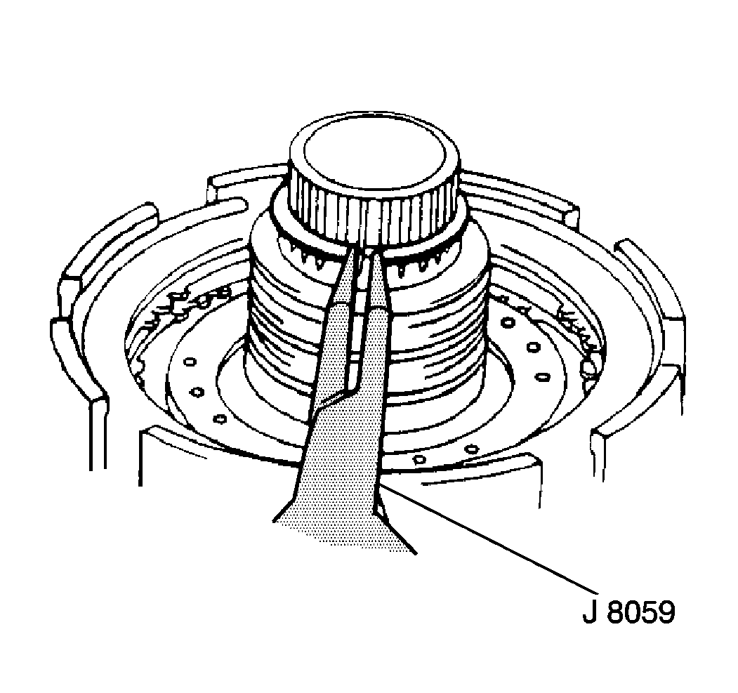
- Remove the planetary gear snap ring using the J 8059 .
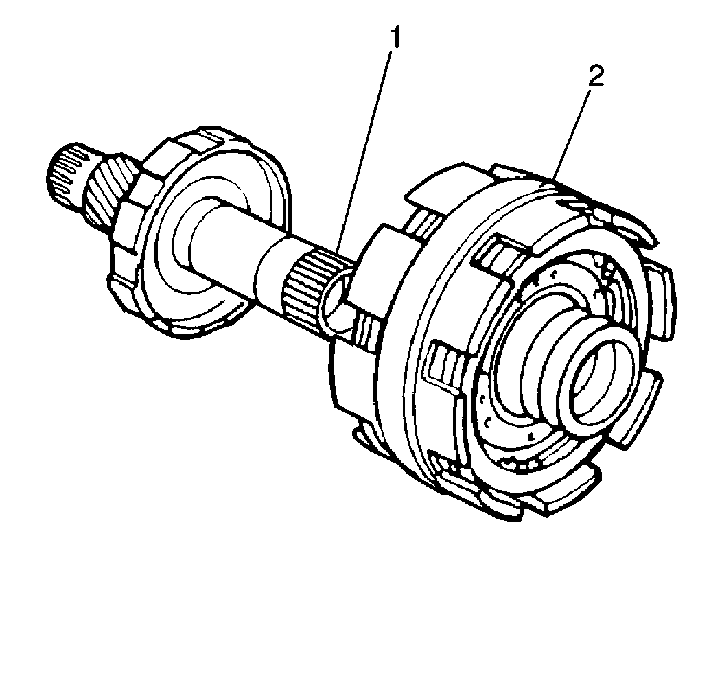
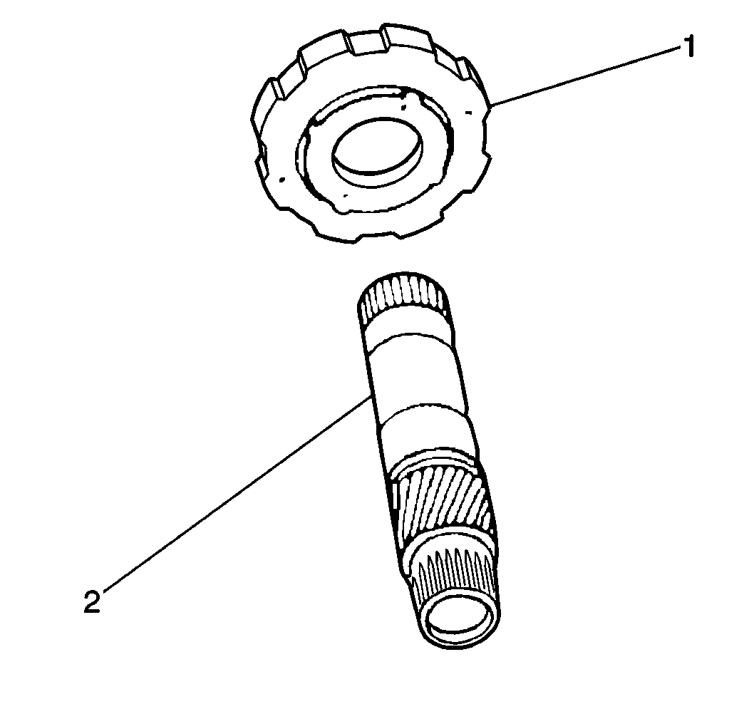
- Remove the planetary gear (1) from the center support (2).
- Measure the B1 brake piston stroke using J 8001 and J 26900-13 :
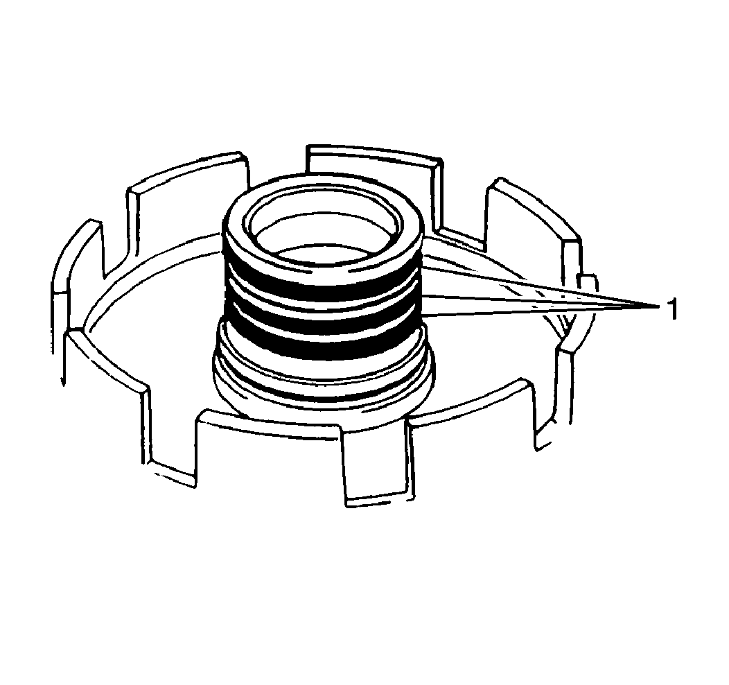
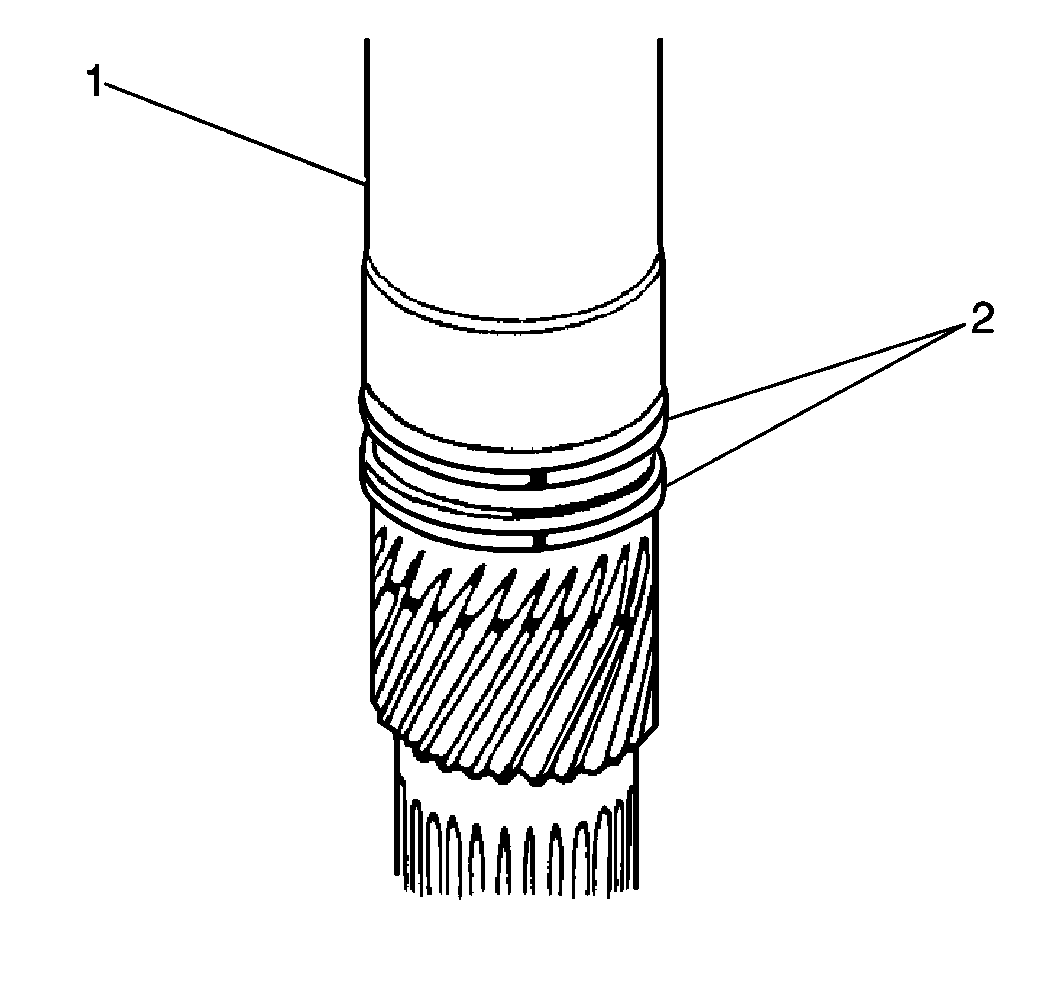
- Remove the 3 rear sealing rings (1) from the center support.
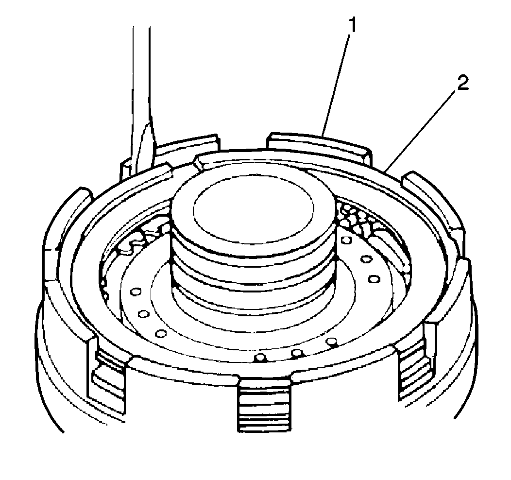
- Remove the B1 brake clutch snap ring (2) from the center support (1) using a flathead screwdriver.
- Remove the following B1 brake components from the center support:
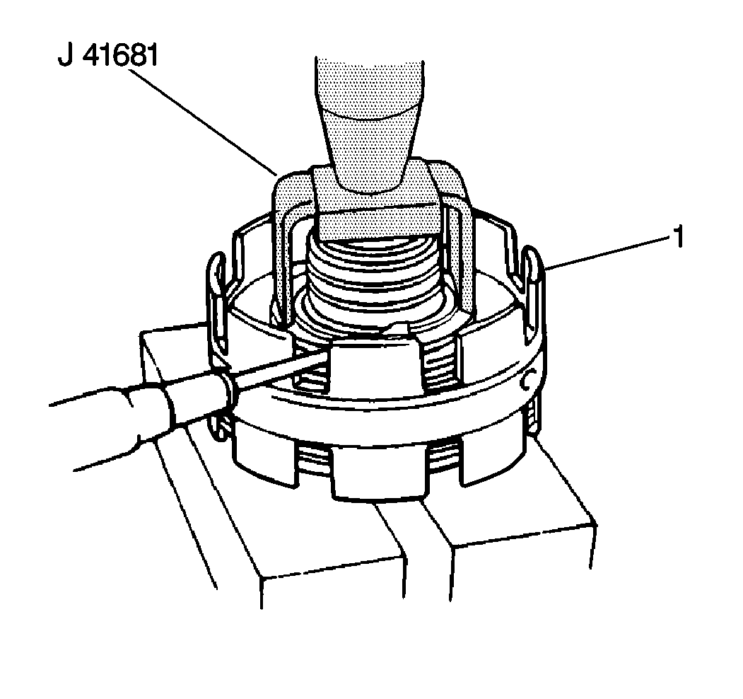
- Remove the B1 brake piston return spring snap ring from the B1 brake piston retainer (1) using J 41681 and a hydraulic press.
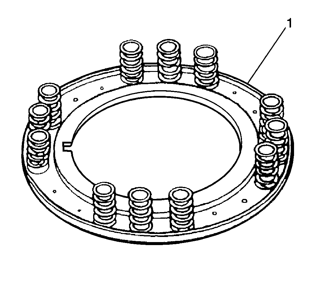
- Remove the B1 brake piston return springs from the center support (1).
- Apply low pressure compressed air to the extreme left fluid passage (1) in order to remove the B1 brake piston.
- Remove the O-rings from the B1 brake piston.
- Measure the B2 brake piston stroke using J 8001 and J 26900-13 :
- Remove the B2 brake snap ring from the center support.
- Remove the following B2 brake components from the center support:
- Remove the B2 brake piston return spring snap ring from the B2 brake piston retainer using the J 41681 and a hydraulic press.
- Remove the B2 brake piston return springs from the center support (1).
- Apply low pressure compressed air to the second left fluid passage (1) in order to remove the B2 brake piston (2).
- Remove the O-rings from the B2 brake piston.
- Perform the following steps in order to inspect the planetary sun gear (4) operation:
- Remove the B2 brake hub assembly (1) from the planetary sun gear (2).
- Remove the two planetary sun gear sealing rings (2).
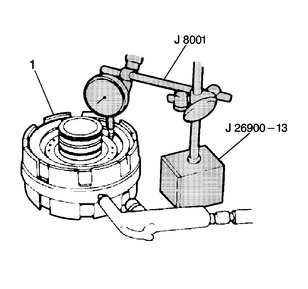
| • | Place the J 8001 plunger on the B1 brake piston. |
| • | Apply 392-785 kPa (57-114 psi) of air pressure into the extreme left overdrive case fluid passage. |
| • | Measure the B1 brake piston stroke. |
Specification
B1 brake piston stroke (standard): 0.63-1.73 mm (0.025-0.068 in)
| • | If the B1 brake piston stroke is not within specifications, replace the brake flange or the disc. |
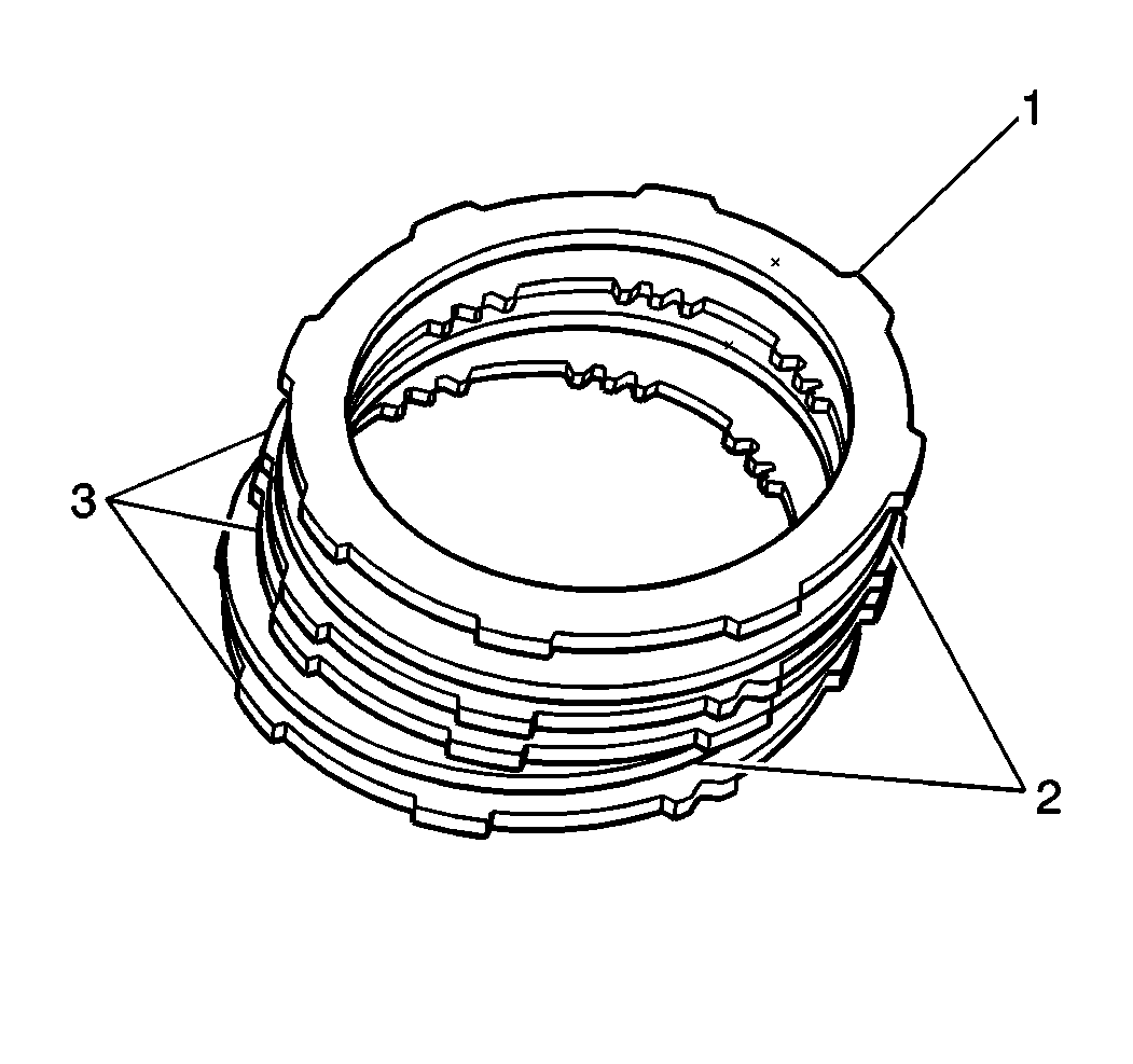
| • | The flange (1) |
| • | The clutch discs (2) |
| • | The clutch plates (3) |
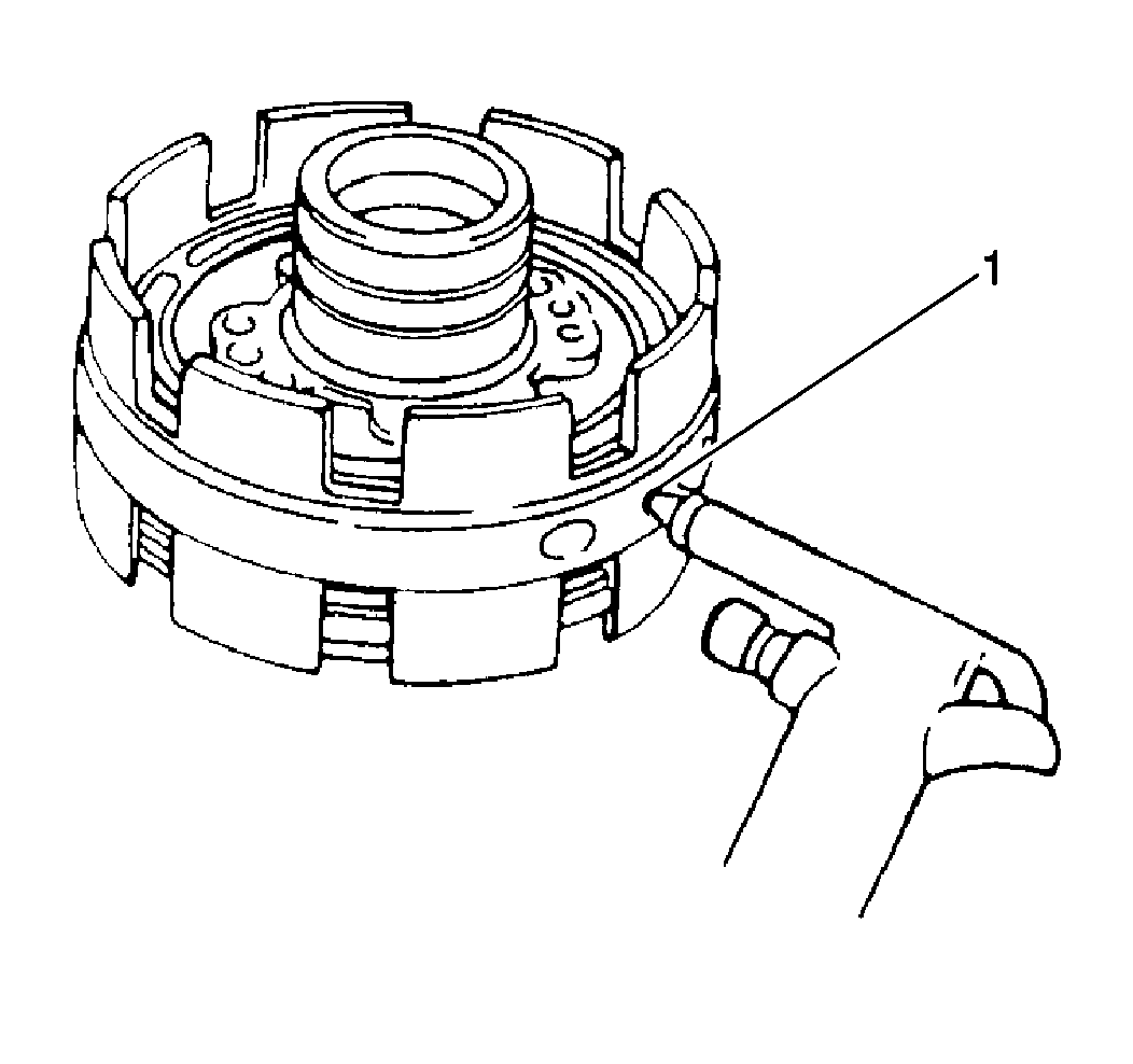
Important: When using compressed air to remove components, air pressure should not exceed 98 kPa (14 psi).
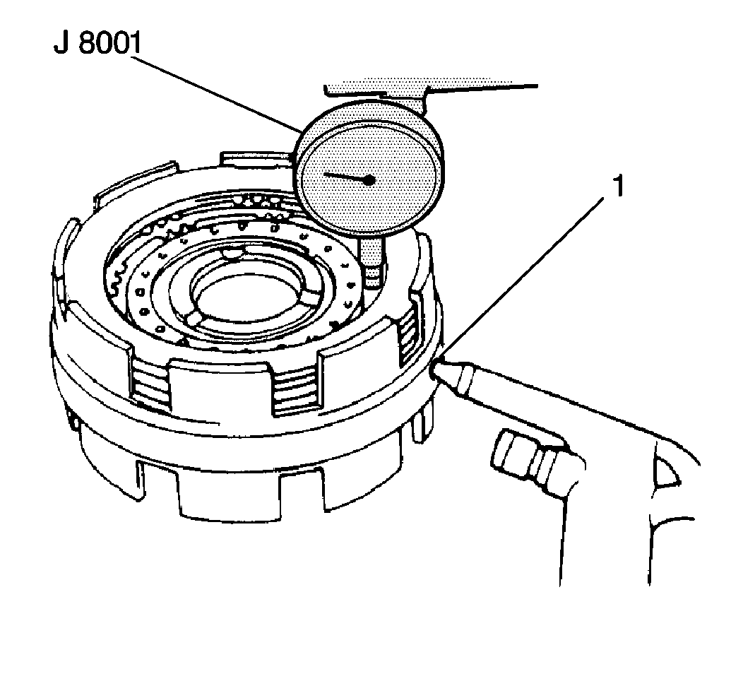
| • | Place the J 8001 plunger on the B2 brake piston. |
| • | Apply 392-785 kPa (57-114 psi) of air pressure into the second left overdrive case fluid passage (1). |
| • | Measure the B2 brake piston stroke. |
Specification
B2 brake piston stroke (standard): 1.01-2.25 mm (0.040-0.088 in)
| • | If the B2 brake piston stroke is not within specifications, replace the brake flange or the disc. |
| • | The flange |
| • | The clutch discs |
| • | The clutch plates |
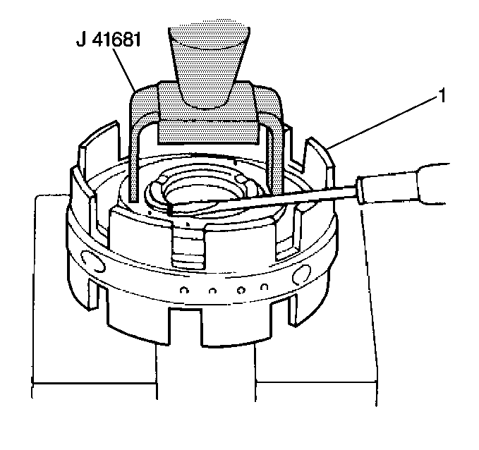
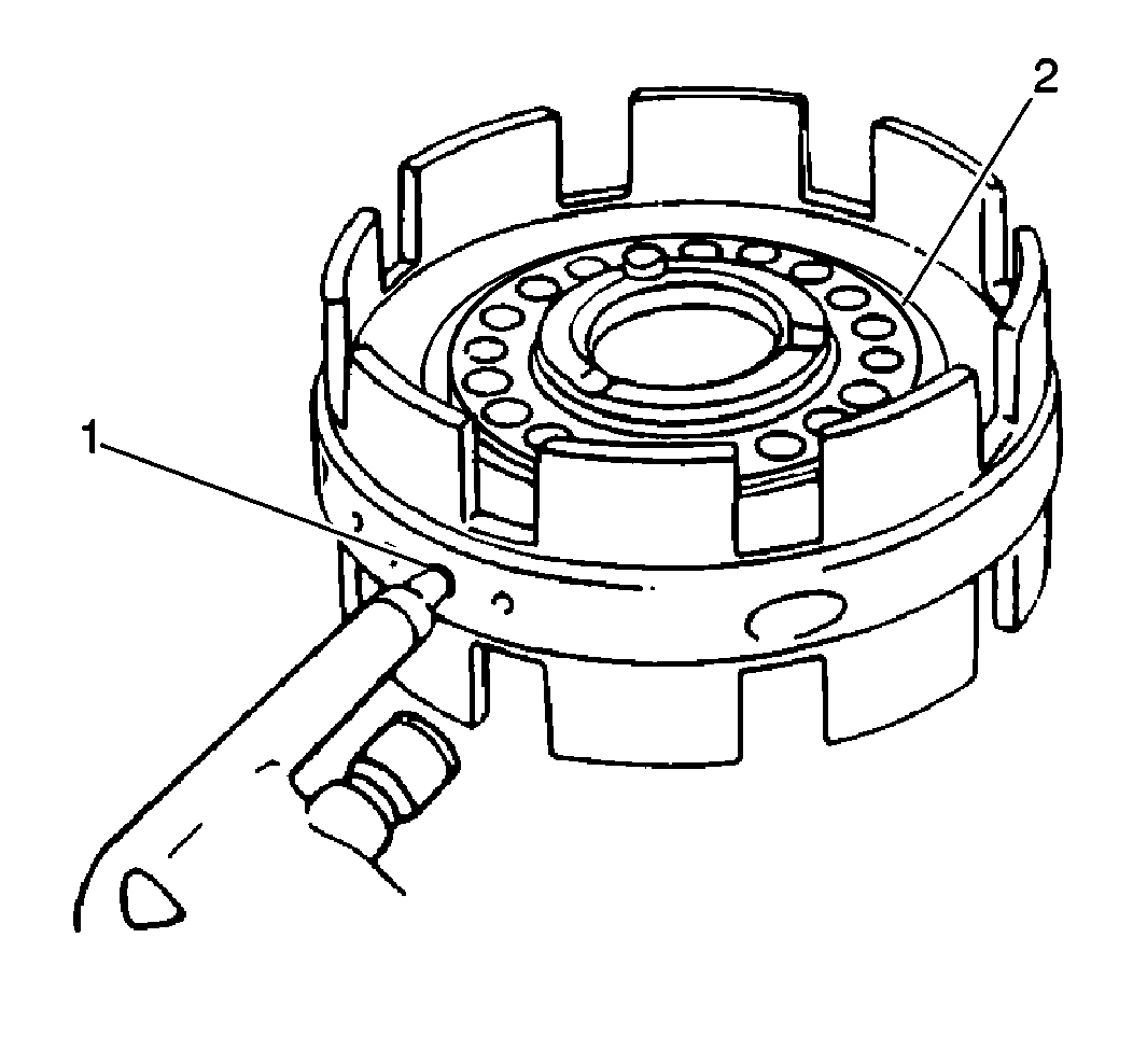
Important: When using compressed air to remove components, air pressure should not exceed 98 kPa (14 psi).
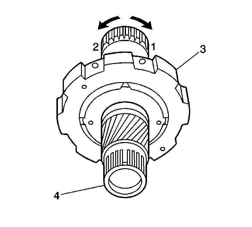
| 18.1. | Hold the B2 brake hub assembly (3). |
| 18.2. | Inspect that the gear locks when turned in the clockwise direction (1). |
| 18.3. | Inspect that the gear turns freely in the counter clockwise direction (2). |
Installation Procedure
- Install the two planetary sun gear seal rings.
- Lubricate the seal rings with A/T fluid.
- Install the B2 brake hub assembly to the planetary sun gear.
- Install 2 new O-rings (1) to the B2 brake piston.
- Lubricate the O-rings with A/T fluid.
- Install the B2 brake piston to the center support.
- Install the B2 brake piston return springs to the B2 brake piston.
- Install the B2 brake piston return spring snap ring onto the B2 piston return spring retainer using J 41681 and a hydraulic press.
- Install the B2 brake plates and discs in the following order:
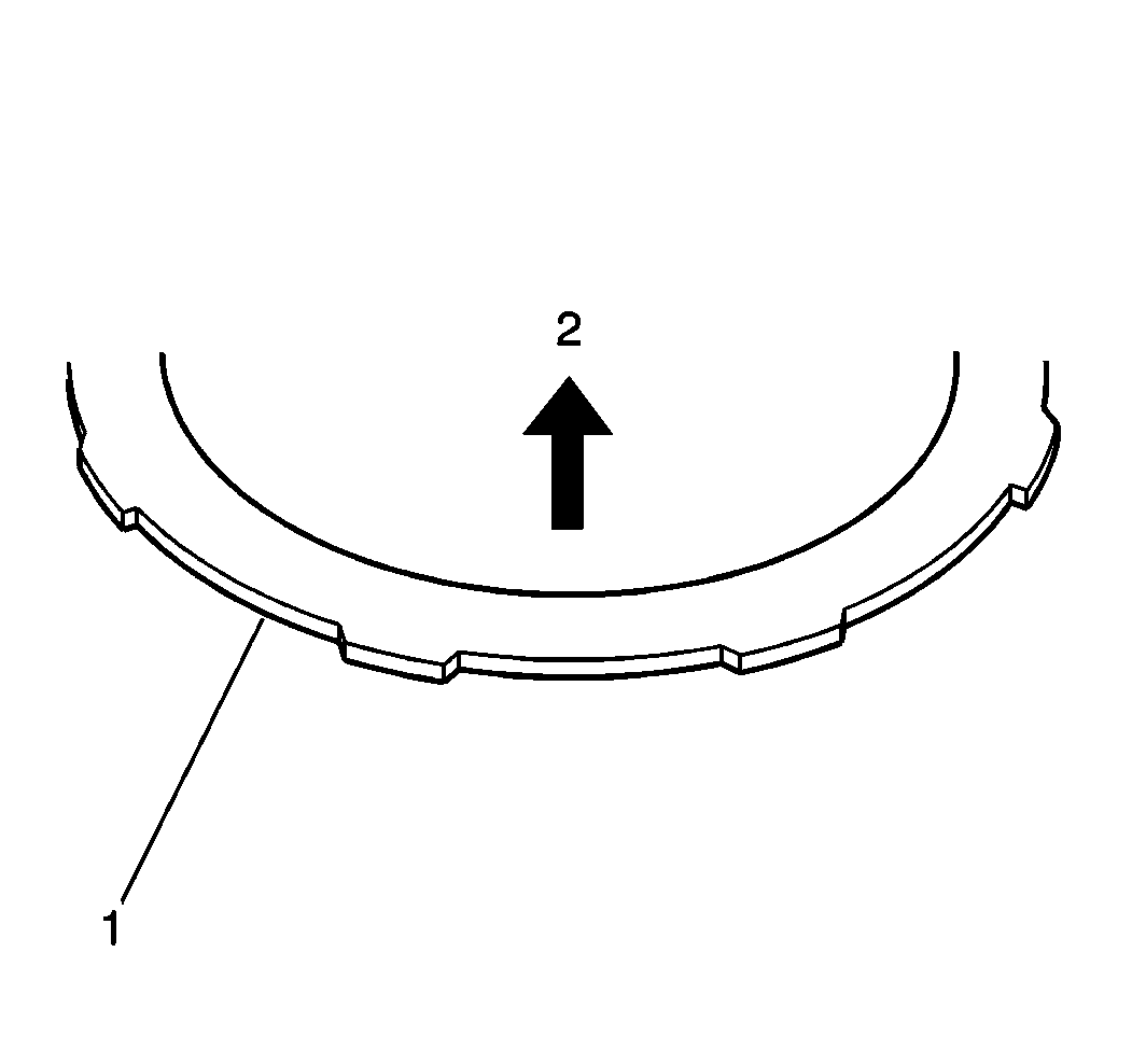
- Install the B2 brake flange (1) with the chamfered side facing the disc (2).
- Install the B2 snap ring into the center support.
- Measure the B2 brake piston stroke using J 8001 and J 26900-13 :
- Install 2 new O-rings to the B1 brake piston.
- Lubricate the O-rings with A/T fluid.
- Install the B1 brake piston to the center support.
- Install the B1 brake piston return springs to the B1 brake piston.
- Install the B1 brake piston return spring snap ring onto the B1 brake piston return spring retainer using J 41681 and a hydraulic press.
- Install the B1 brake plates and discs in the following order:
- Install the B1 brake flange with the chamfered side facing the disc.
- Install the B1 snap ring into the center support.
- Measure the B1 brake piston (1) stroke using J 8001 and J 26900-13 :
- Install the three rear seal rings to the center support.
- Lubricate the seal rings with A/T fluid.
- Install the planetary gear to the center support.
- Install the planetary gear snap ring using J 8059 .
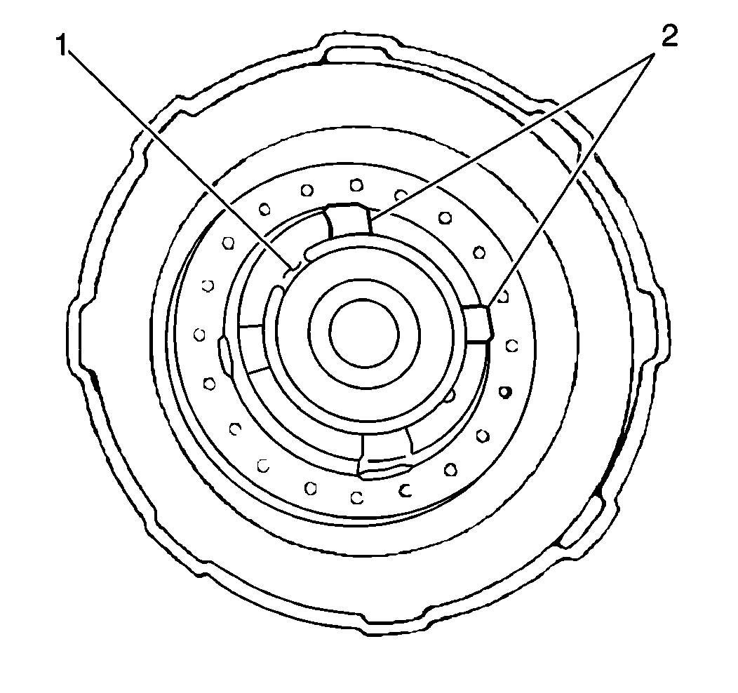
Important: Do not align the snap ring opening with B2 brake piston return spring retainer lug (2) during the next step.
| 9.1. | The plate |
| 9.2. | The disc |
| 9.3. | The plate |
| 9.4. | The disc |
| 9.5. | The plate |
| 9.6. | The disc |

| • | Place J 8001 plunger on the B2 brake piston. |
| • | Apply 392-785 kPa (57-114 psi) of air pressure into the second left overdrive case fluid passage (1) . |
| • | Take the measurement. |
Specification
B2 brake piston stroke (standard): 1.01-2.25 mm (0.040-0.088 in)
| • | If the B2 brake piston stroke is not within specifications, disassemble and inspect. |
| 18.1. | The plate |
| 18.2. | The disc |
| 18.3. | The plate |
| 18.4. | The plate |
| 18.5. | The disc |

| • | Place the J 8001 plunger on the B1 brake piston. |
| • | Apply 392-785 kPa (57-114 psi) of air pressure into the extreme left overdrive case fluid passage. |
| • | Take the measurement. |
Specification
B1 brake piston stroke (standard): 0.63-1.73 mm (0.025-0.068 in)
| • | If the B1 brake piston stroke is not within specifications, disassemble and inspect. |
