Battery Replacement C4/C5 - Single Battery
Removal Procedure
- Disconnect the negative battery cable. Refer to Battery Negative Cable Disconnection and Connection.
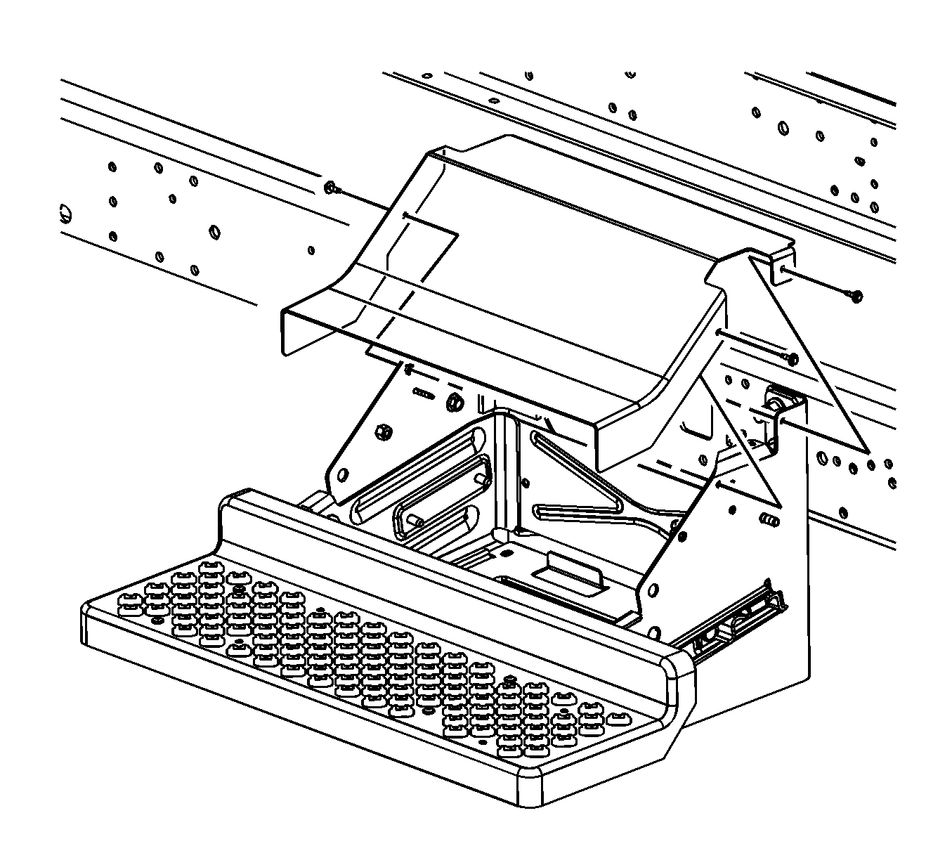
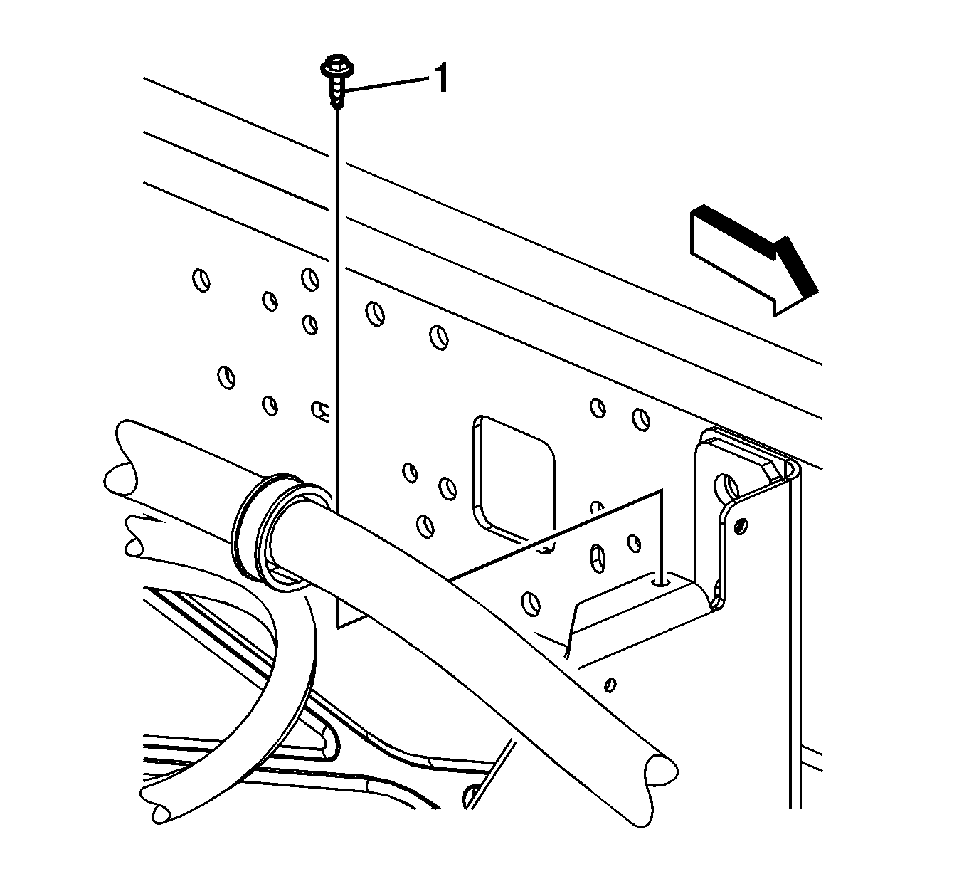
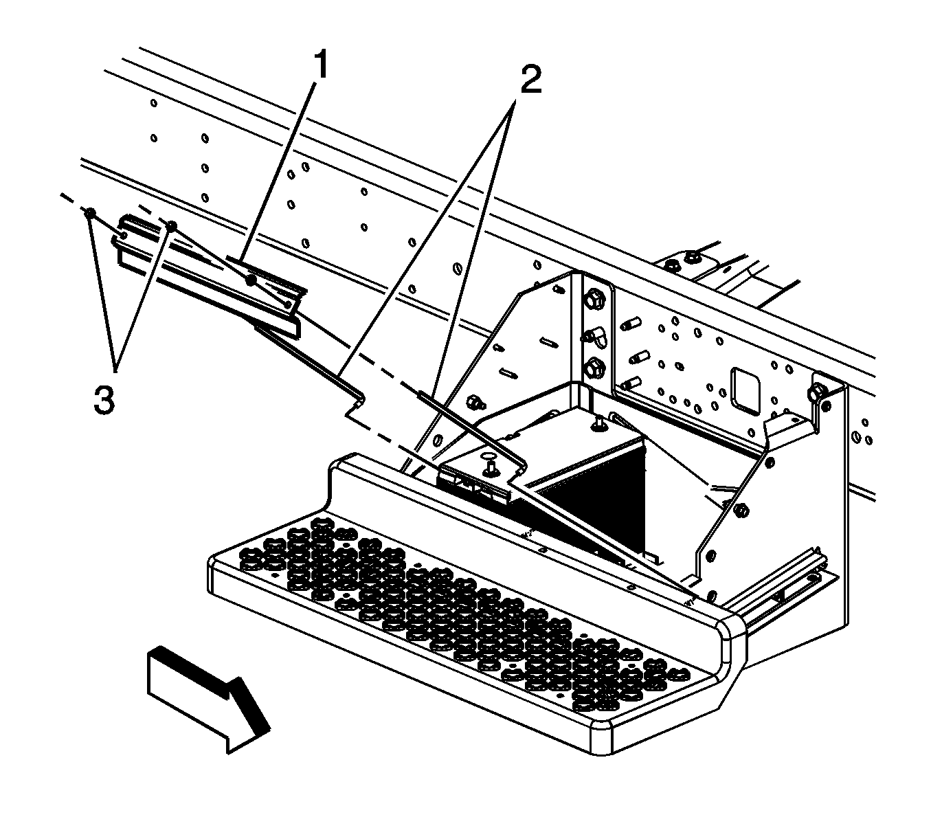
- Remove the battery cover bolts and cover, if required.
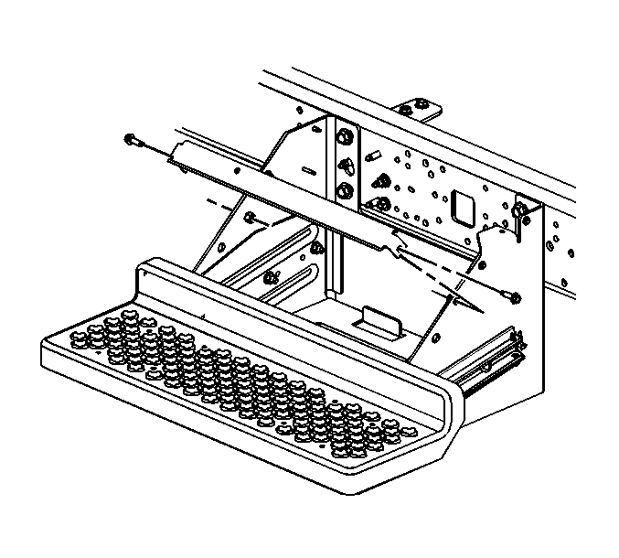
- If equipped without regular production options (RPO's) ANC/B3D, remove the battery tray support bolts and support.
- If equipped with a side post battery perform the following steps, otherwise proceed to step 13.
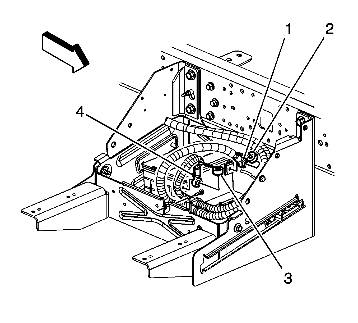
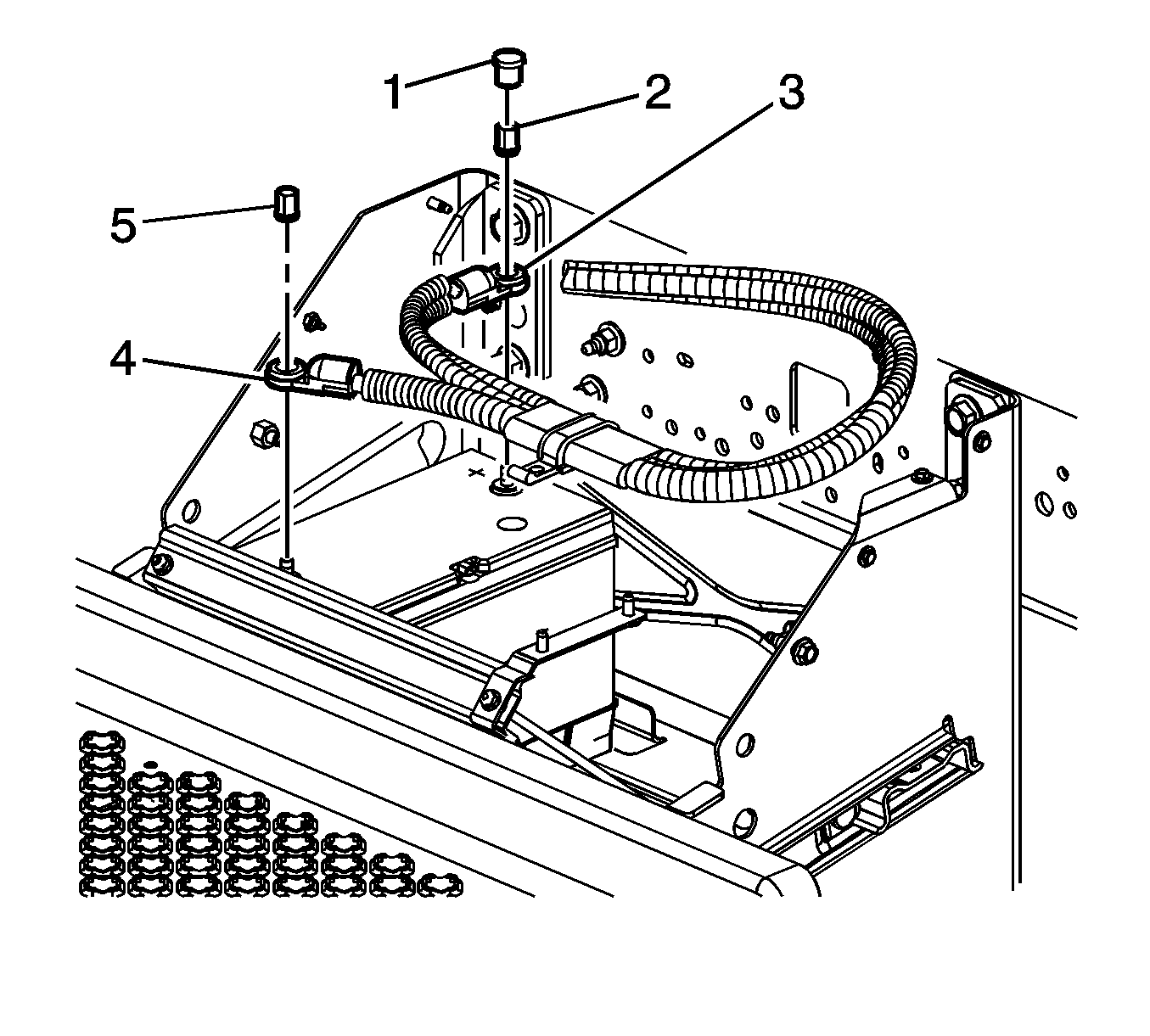
- Open the positive battery cable cover (3).
- Loosen the positive battery cable bolt (4).
- Reposition the positive battery cable from the battery.
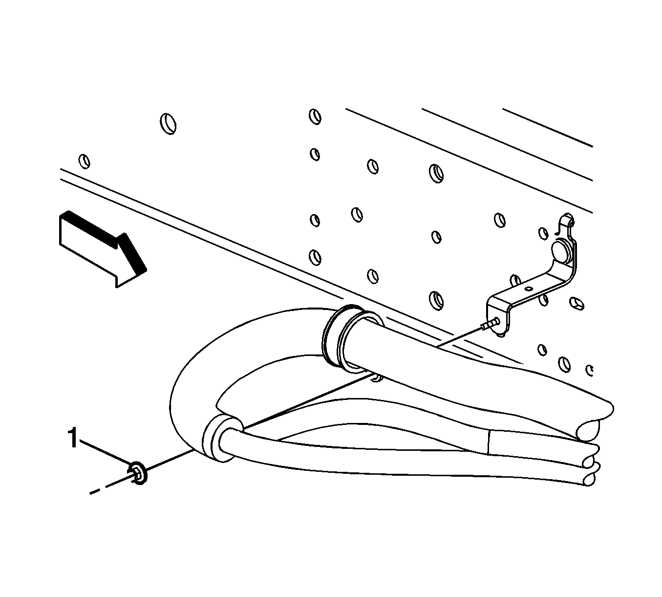
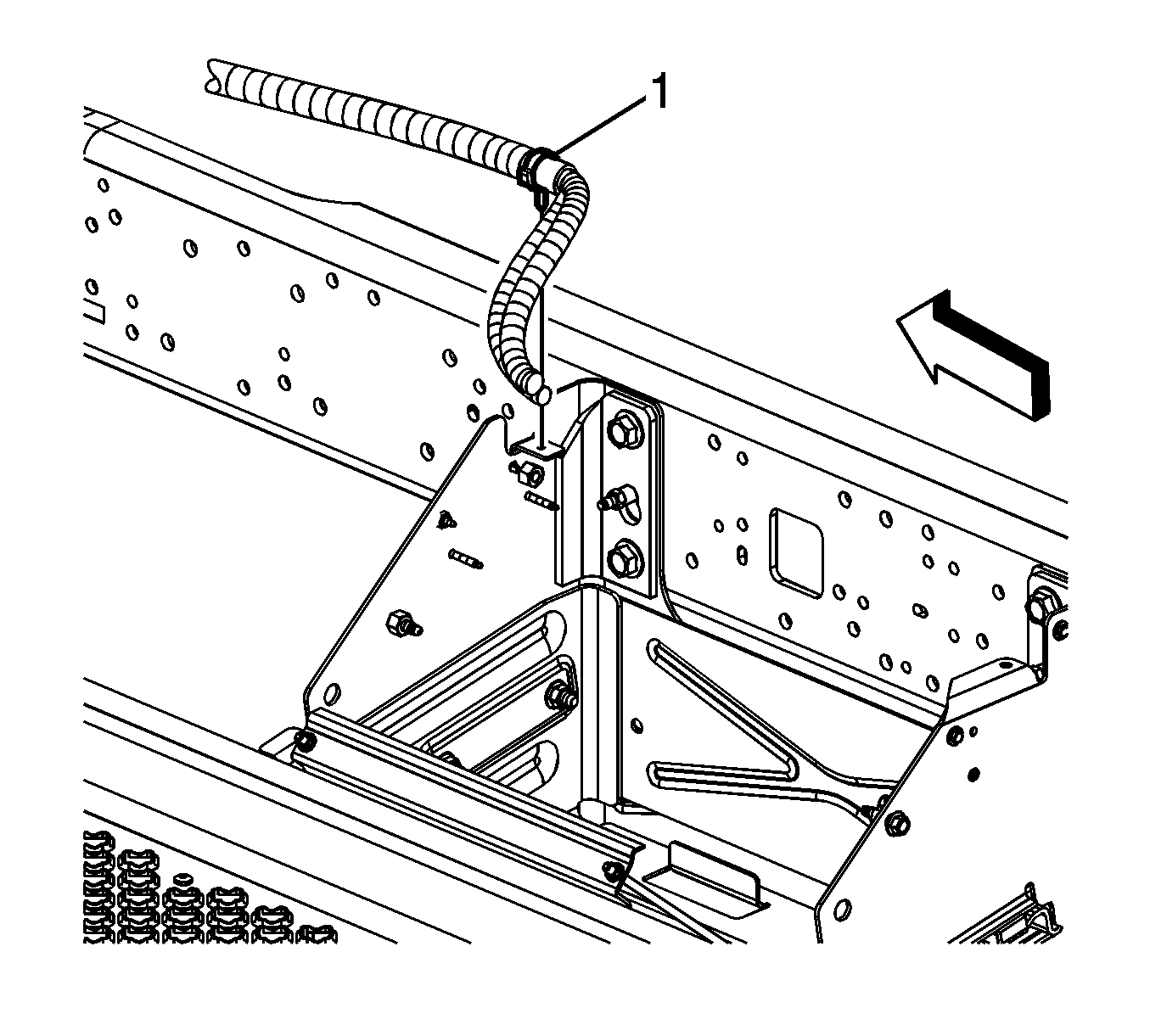
- Remove the battery cable clip nut (1), if required.
- Remove the battery cable clip bolt (1), if required.
- Reposition the battery cables as required.
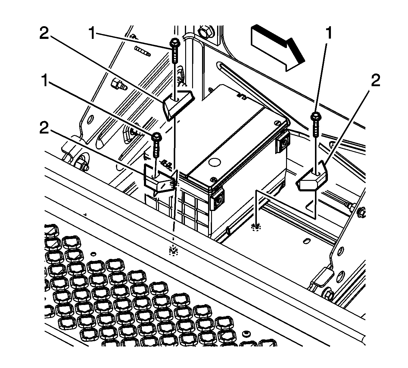
- Remove the battery hold down retainer bolts (1) and retainers (2).
- Remove the battery.
- If equipped with top post battery perform the following steps, remove the positive battery cable nut cover (1).
- Remove the positive battery cable nut (2).
- Remove the positive battery cable (3) from the battery.
- Remove the battery cable clip (1) from the battery tray bracket, if required.
- Reposition the battery cables as required.
- Remove the battery hold down retainer nuts (3), retainer (1), and retainer studs (2).
- Remove the battery.
Installation Procedure
- If equipped with a side post battery perform the following steps, otherwise proceed to step 10.
- Install the battery.
- Install the battery hold down retainers (2) and bolts (1).
- Position the battery cables as required.
- Install the battery cable clip bolt (1), if required.
- Install the battery cable clip nut (1), if required.
- Position the positive battery cable to the battery.
- Tighten the positive battery cable bolt (4).
- Close the positive battery cable cover (3). Proceed to step 17.
- If equipped with top post battery perform the following steps, install the battery.
- Install the battery hold down retainer studs (2), retainer (1) and nuts (3).
- Position the battery cables as required.
- Install the battery cable clip (1) to the battery tray bracket, if required.
- Install the positive battery cable (3) to the battery.
- Install the positive battery cable nut (2).
- Install the positive battery cable nut cover (1).
- If equipped without RPO's ANC/B3D, install the battery tray support and bolts.
- Install the battery cover and bolts, if required.
- Connect the negative battery cable. Refer to Battery Negative Cable Disconnection and Connection.

Caution: Refer to Fastener Caution in the Preface section.
Tighten
Tighten the bolt to 25 N·m (18 lb ft).

Tighten
Tighten the bolt to 25 N·m (18 lb ft).

Tighten
Tighten the nut to 25 N·m (18 lb ft).

Tighten
Tighten the bolt to 17 N·m (13 lb ft).

Tighten
Tighten the nuts to 10 N·m (89 lb in).


Tighten
Tighten the nut to 22 N·m (16 lb ft).

Tighten
Tighten the bolts to 25 N·m (18 lb ft).

Tighten
Tighten the bolts to 11 N·m (97 lb in).
Battery Replacement C 6/7/8
Removal Procedure
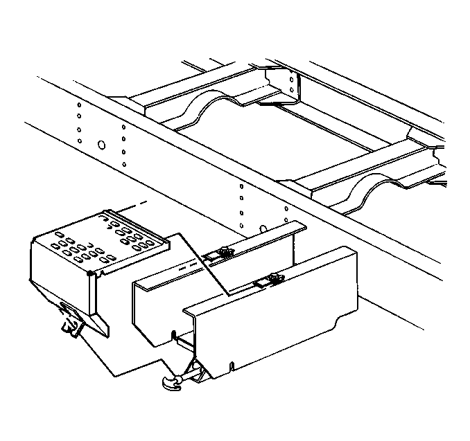
- Remove the battery carrier cover.
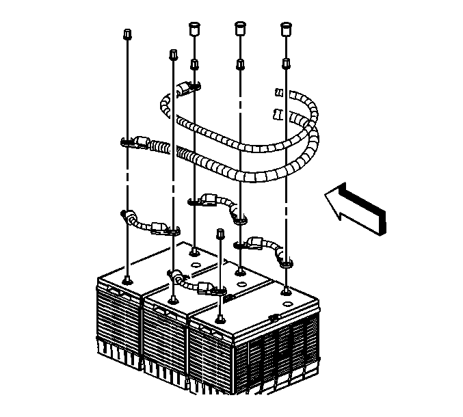
- Disconnect the negative cable from the negative battery terminal.
- Disconnect the positive cable from the positive battery terminal.
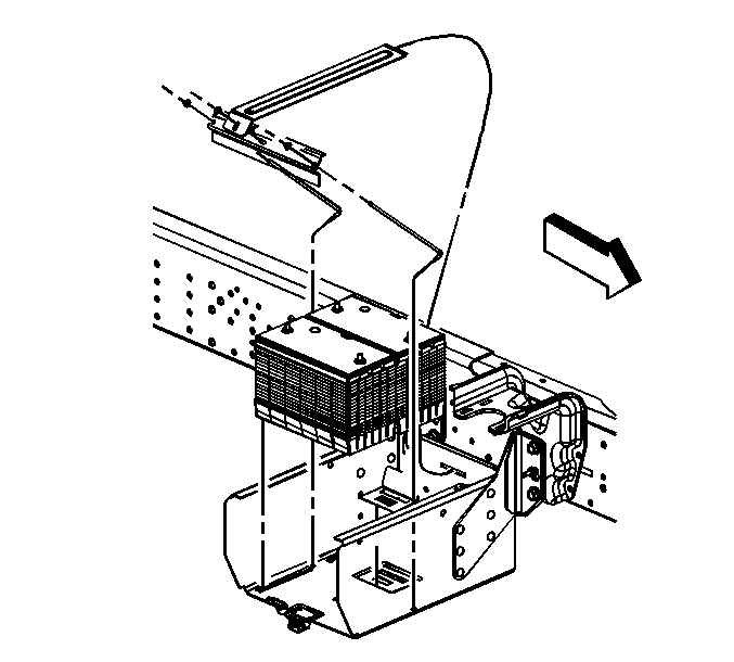
- Remove the battery hold-down retainer nut or bolt.
- Remove the battery from the carrier.
- Inspect the following components for damage:
| • | The battery |
| • | The cables |
| • | The connectors |
| • | Verify that the carrier is free from damage or foreign objects. |
| • | Find and correct the cause of damage if any damage is noted. |
| • | Clean the parts as necessary. |
Installation Procedure
- Install the battery into the cleaned carrier.
- Install the battery hold-down retainer or top bar.
- Install the hold-down nut or the bolt.
- Connect the positive cable to the positive battery terminal.
- Connect the negative cable to the negative battery terminal.
- Install the battery carrier cover.

Caution: Refer to Fastener Caution in the Preface section.
Tighten
| • | Tighten the battery hold-down bolt to 23 N·m (17 lb ft). |
| • | Tighten the top bar nut to 17 N·m (13 lb ft). |
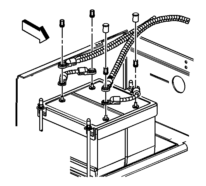
Tighten
| • | Tighten the side post terminal bolt to 15 N·m (11 lb ft). |
| • | Tighten the top post terminal nut to 17 N·m (13 lb ft). |

Battery Replacement C4/C5 - Dual Batteries
Removal Procedure
- Disconnect the negative battery cable. Refer to Battery Negative Cable Disconnection and Connection.
- Remove the battery cover bolts and cover, if required.
- If equipped without regular production options (RPO's) ANC/B3D, remove the battery tray support bolts and support.
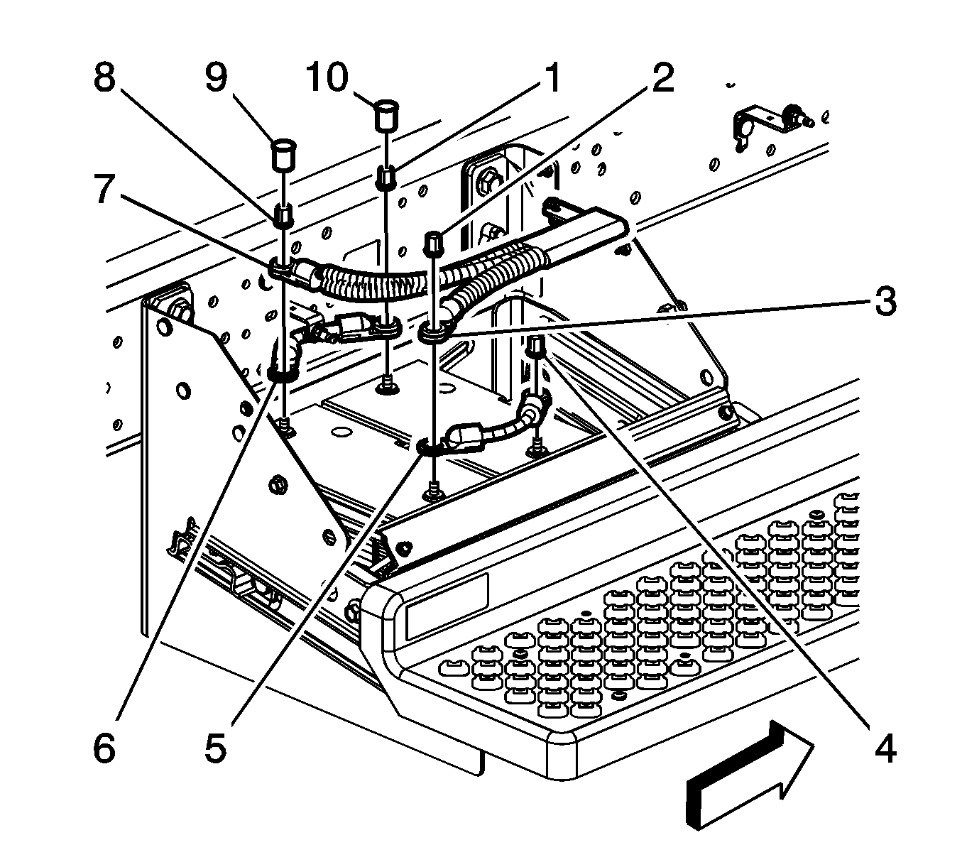
- Remove the negative battery cable nut (4).
- Remove the negative battery cable (5) from the second battery.
- Remove the positive battery cable nut covers (10).
- Remove the positive battery cable nuts (1 and 8).
- Remove the positive battery cable (7) from the first battery.
- Remove the positive battery cable (6) from the first and second battery.
- Remove the battery cable clip nut (1), if required.
- Remove the battery cable clip bolt (1), if required.
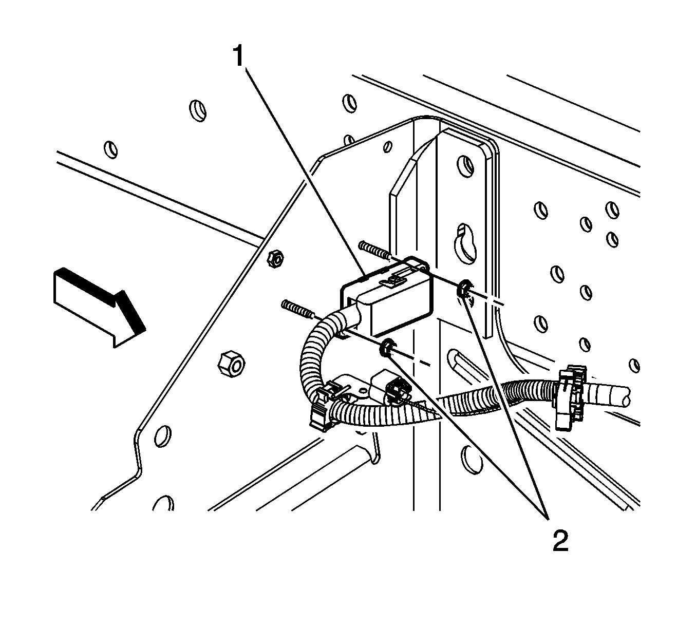
- Remove the auxiliary battery cable junction block nuts (2).
- Remove the auxiliary battery cable junction block (1) from the studs.
- Disconnect the electrical connector from the auxiliary battery cable electrical connector.
- Reposition the auxiliary and 12 volt battery cables as required.
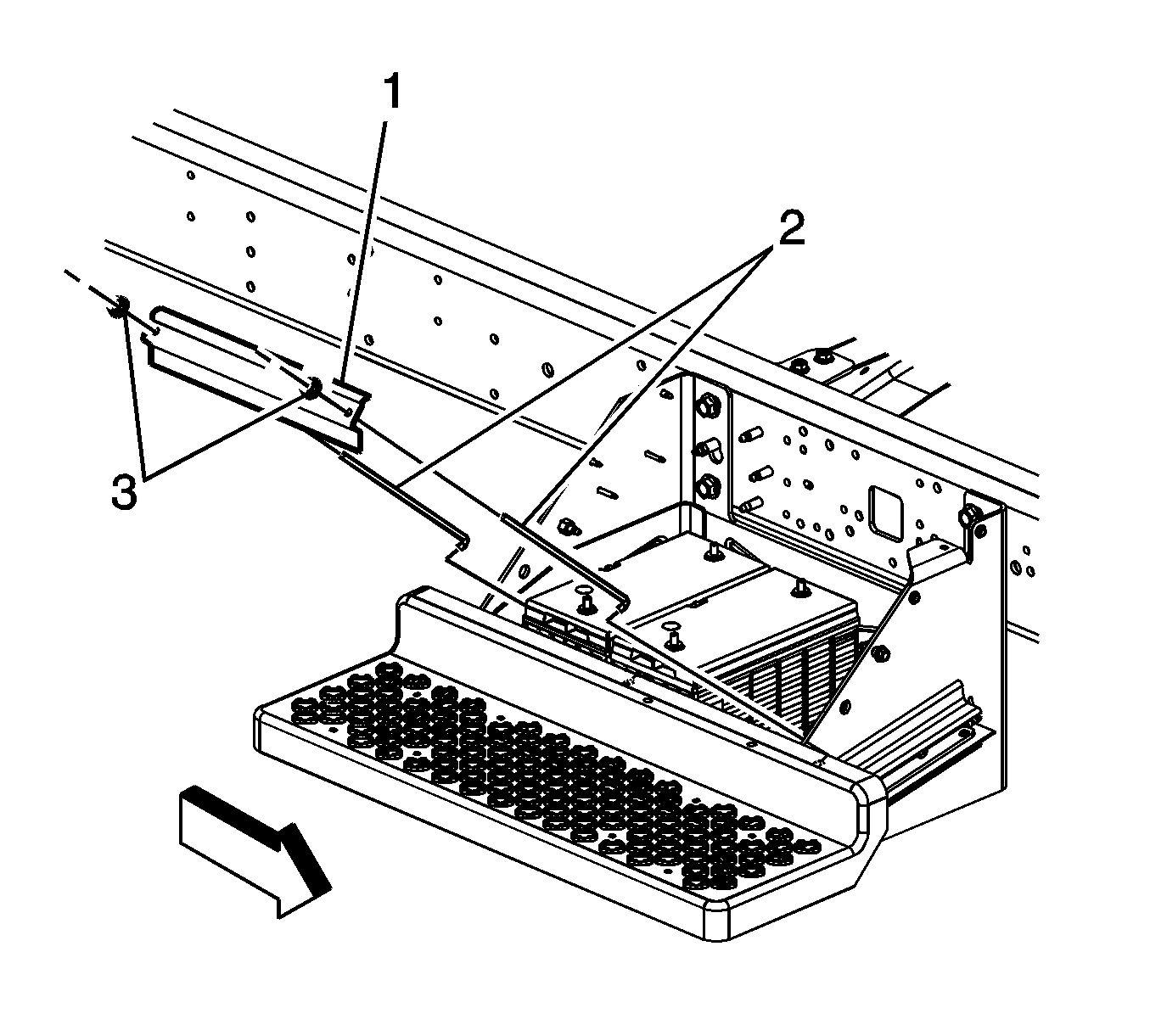
- Remove the battery hold down retainer nuts (3), retainer (1) and retainer studs (2).
- Remove the appropriate battery.




Installation Procedure
- Install the appropriate battery.
- Install the battery hold down retainer studs (2), retainer (1), and nuts (3).
- Position the auxiliary and 12 volt battery cables as required.
- Install the auxiliary battery cable junction block (1) to the studs.
- Install the auxiliary battery cable junction block nuts (2).
- Connect the electrical connector to the auxiliary battery cable electrical connector.
- Install the battery cable clip bolt (1), if required.
- Install the battery cable clip nut (1), if required.
- Install the positive battery cable (6) to the first and second batteries.
- Install the positive battery cable (7) to the first battery.
- Install the positive battery cable nuts (1 and 8).
- Install the positive battery cable nut covers (10).
- Install the negative battery cable (5) to the second battery.
- Install the negative battery cable nut (4).
- If equipped without RPO's ANC/B3D, install the battery tray support and bolts.
- Install the battery cover and bolts, if required.
- Connect the negative battery cable. Refer to Battery Negative Cable Disconnection and Connection.

Caution: Refer to Fastener Caution in the Preface section.
Tighten
Tighten the nuts to 10 N·m (89 lb in).

Tighten
Tighten the nuts to 4.5 N·m (40 lb in).

Tighten
Tighten the bolt to 25 N·m (18 lb ft).

Tighten
Tighten the nut to 25 N·m (18 lb ft).

Tighten
Tighten the nuts to 22 N·m (16 lb ft).
Tighten
Tighten the nut to 22 N·m (16 lb ft).

Tighten
Tighten the bolts to 25 N·m (18 lb ft).

Tighten
Tighten the bolts to 11 N·m (97 lb in).
Battery Replacement C4/C5 - Triple Batteries
Removal Procedure
- Disconnect the negative battery cable. Refer to Battery Negative Cable Disconnection and Connection.
- Remove the battery cover bolts and cover, if required.
- If equipped without regular production options (RPO's) ANC/B3D, remove the battery tray support bolts and support.
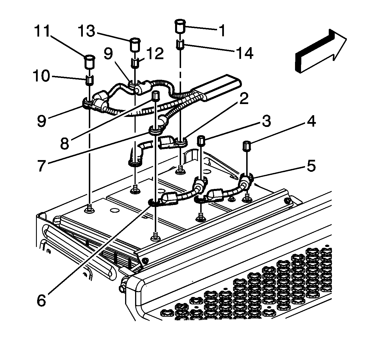
- Remove the negative battery cable nut (4).
- Remove the negative battery cable (5) from the second and third batteries.
- Remove the positive battery cable nut covers (1, 11, and 13).
- Remove the positive battery cable nuts (10, 12, and 14).
- Remove the positive battery cable (9) from the first and second batteries.
- Remove the positive battery cable (2) from the second and third batteries.
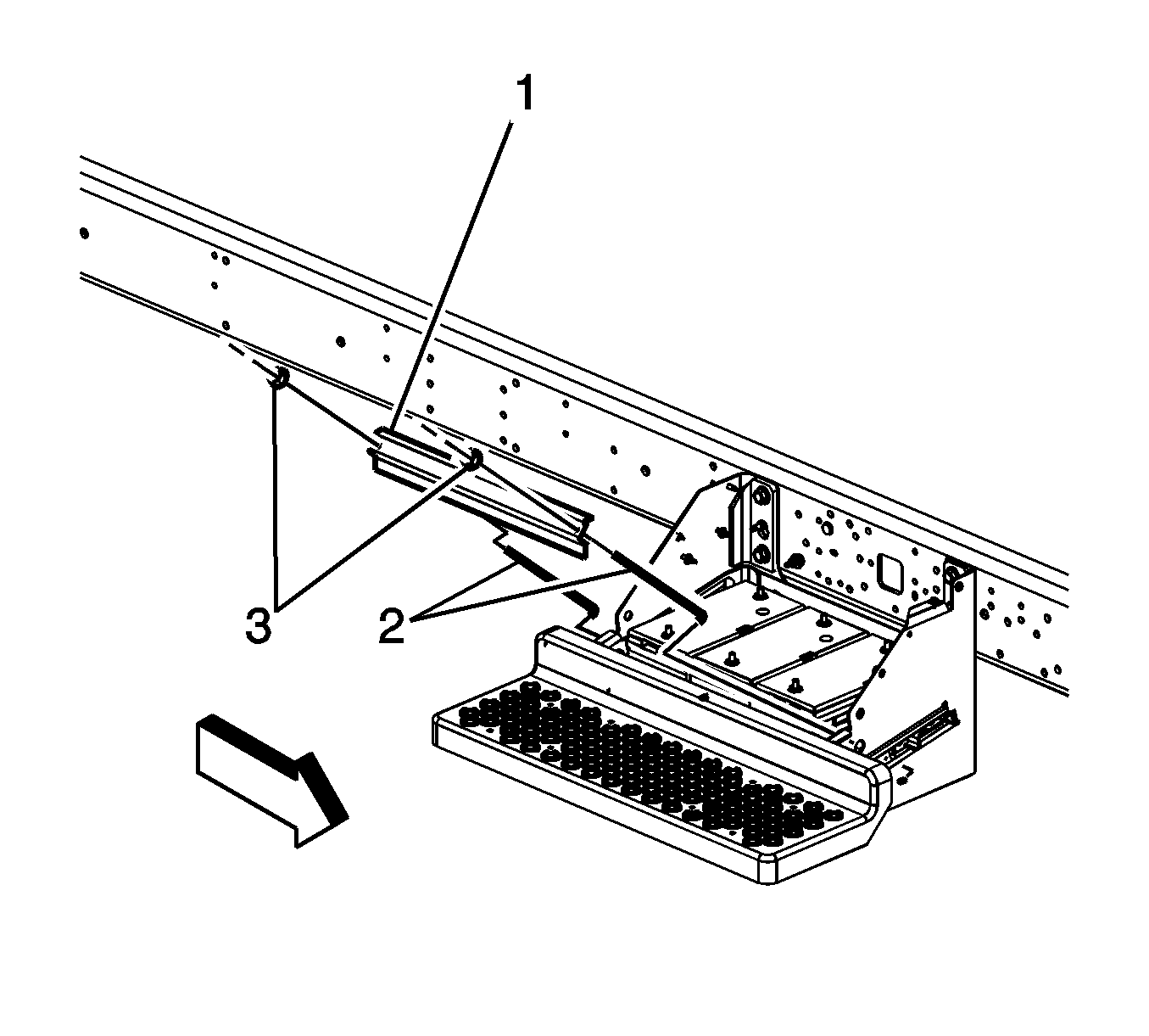
- Remove the battery cable clip nut (1), if required.
- Remove the battery cable clip bolt (1), if required.
- Remove the auxiliary battery cable junction block nuts (2).
- Remove the auxiliary battery cable junction block (1) from the studs.
- Disconnect the electrical connector from the auxiliary battery cable electrical connector.
- Reposition the auxiliary and 12 volt battery cables as required.
- Remove the battery hold down retainer nuts (3), retainer (1) and retainer studs (2).
- Remove the appropriate battery.




Installation Procedure
- Install the appropriate battery.
- Install the battery hold down retainer studs (2), retainer (1), and nuts (3).
- Position the auxiliary and 12 volt battery cables as required.
- Install the auxiliary battery cable junction block (1) to the studs.
- Install the auxiliary battery cable junction block nuts (2).
- Connect the electrical connector to the auxiliary battery cable electrical connector.
- Install the battery cable clip bolt (1), if required.
- Install the battery cable clip nut (1), if required.
- Install the positive battery cable (2) to the second and third batteries.
- Install the positive battery cable (9) to the first and second batteries.
- Install the positive battery cable nuts (10, 12, and 14).
- Install the positive battery cable nut covers (1, 11, and 13).
- Install the negative battery cable (5) to the second and third batteries.
- Install the negative battery cable nut (4).
- If equipped without RPO's ANC/B3D, install the battery tray support and bolts.
- Install the battery cover and bolts, if required.
- Connect the negative battery cable. Refer to Battery Negative Cable Disconnection and Connection.

Caution: Refer to Fastener Caution in the Preface section.
Tighten
Tighten the nuts to 10 N·m (89 lb in).

Tighten
Tighten the nuts to 4.5 N·m (40 lb in).

Tighten
Tighten the bolt to 25 N·m (18 lb ft).

Tighten
Tighten the nut to 25 N·m (18 lb ft).

Tighten
Tighten the nuts to 22 N·m (16 lb ft).
Tighten
Tighten the nuts to 22 N·m (16 lb ft).

Tighten
Tighten the bolts to 25 N·m (18 lb ft).

Tighten
Tighten the bolts to 11 N·m (97 lb in).
