For 1990-2009 cars only
Fuel Injection Pump Replacement w/o CTF
Removal Procedure
- Ensure that the Number 1 cylinder is at top dead center of the compression stroke.
- Remove the engine cover. Refer to Engine Cover Replacement .
- Disconnect the engine harness connector from the fuel pump and sensor.
- If equipped, remove the brake hose clip and reposition the brake hoses.
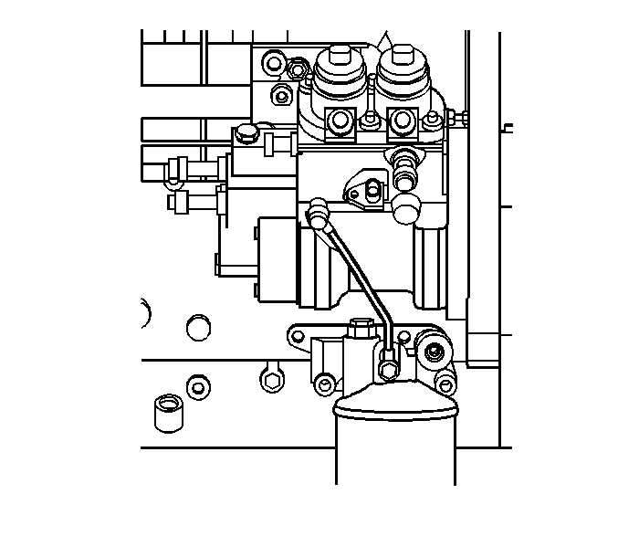
- Remove the oil feed pipe.
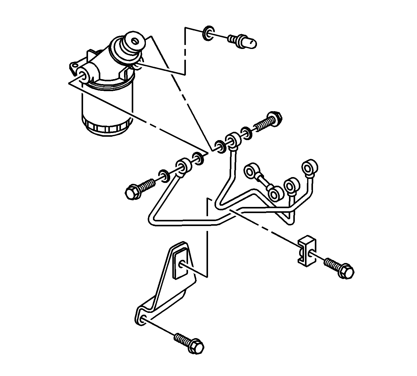
- Remove the 2 fuel feed pipes to the common rail.
- Remove the fuel feed pipe from the fuel filter to the pump.
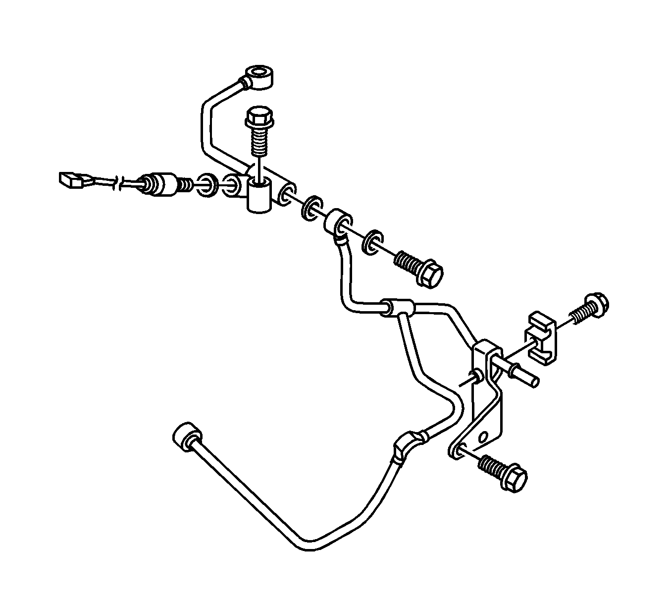
- Remove the fuel return pipes bracket bolts.
- Remove the fuel return pipe at the three-point ("T," Rail, Pump).
- Remove the fuel pump feed crossover pipe from the fuel pump.
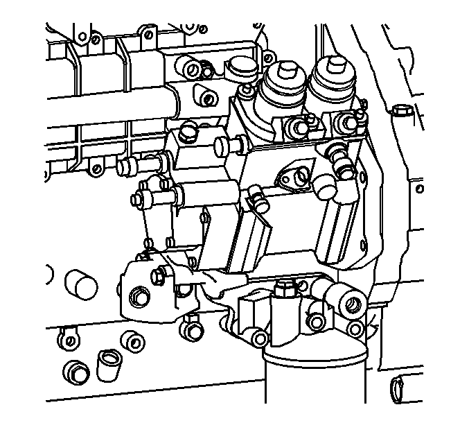
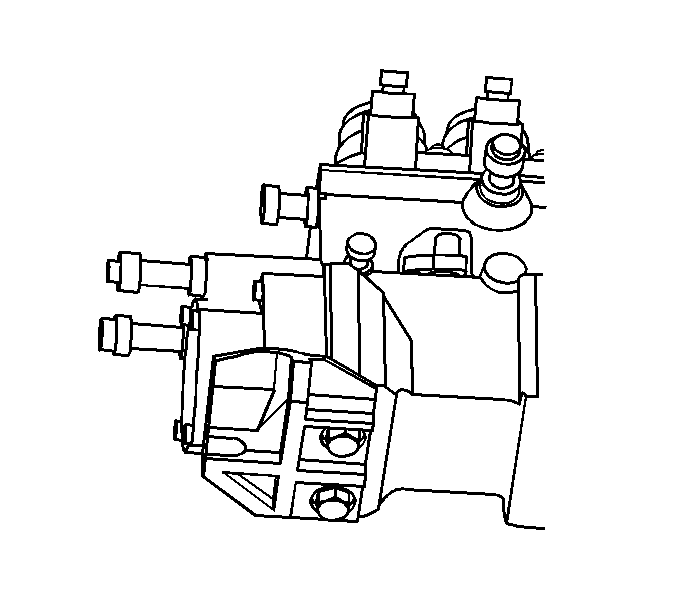
- Remove the fuel supply pump bracket from the cylinder block.
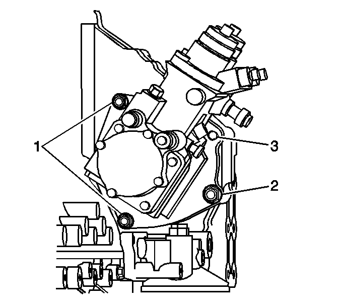
- Remove the fuel supply pump with adapter nuts (1, 2), bolt (3) and pump/with adapter from the engine.
- Remove the fuel supply pump bracket under a fuel supply pump.
- Remove the gear and key from the shaft in the fuel supply pump.
Installation Procedure
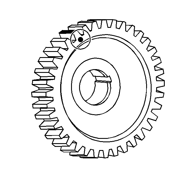
- Paint the gear surface of the punch mark.
- Attach the key to shaft of the fuel supply pump.
- Tighten the gear with nut and washer.
- Install the fuel supply pump bracket to the button of fuel supply pump.
- Install the bracket bolt.
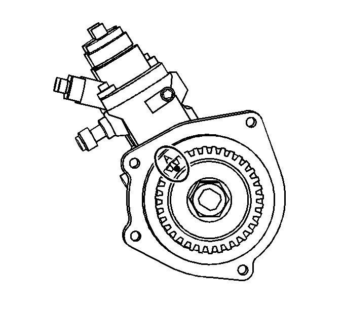
- Align the fuel supply pump mark A and the gear punch mark.
- Number 1 cylinder should be at top dead center.
- Fit the O-ring to fuel supply pump.
- Install the fuel supply pump to the cylinder block.
- Tighten the fuel supply pump nut and bolt to the following torques:
- Inspect the gear position from inspection hole on housing upper part.
- Confirm that the gear paint mark is centered in the inspection hole as zoom view. If not, re-time the gears and reinstall the fuel supply pump.
- Install the fuel supply pump bracket to the cylinder block.
- Install the plug to the inspection hole.
- Tighten the fuel supply pump bracket bolt and plug to the following torques:
- Install the oil feed pipe.
- Tighten the eye bolt to the following torques:
- Install the fuel pump feed crossover pipe to the fuel pump.
- Install the fuel return pipe at the rail, pump and fuel "T."
- Install the fuel return pipe bracket.
- Install the fuel feed to the fuel filter and fuel pump.
- Install the fuel pipes to the common rail.
- If repositioned, reinstall the brake hoses and secure with fasteners.
- Connect all electrical connectors at the pump and sensors.
- Install the engine cover. Refer to Engine Cover Replacement .
Notice: Refer to Fastener Notice in the Preface section.
Tighten
Tighten the fuel supply pump nut to 270 N·m (199 lb ft).

Tighten
Tighten the fuel supply pump bracket bolt to 56.8 N·m (41.9 lb ft).

Tighten
| • | Nut (1) to 40.2 N·m (29.7 lb ft) |
| • | Nut (2) to 72.5 N·m (53.5 lb ft) |
| • | Bolt (3) to 72.5 N·m (53.5 lb ft) |
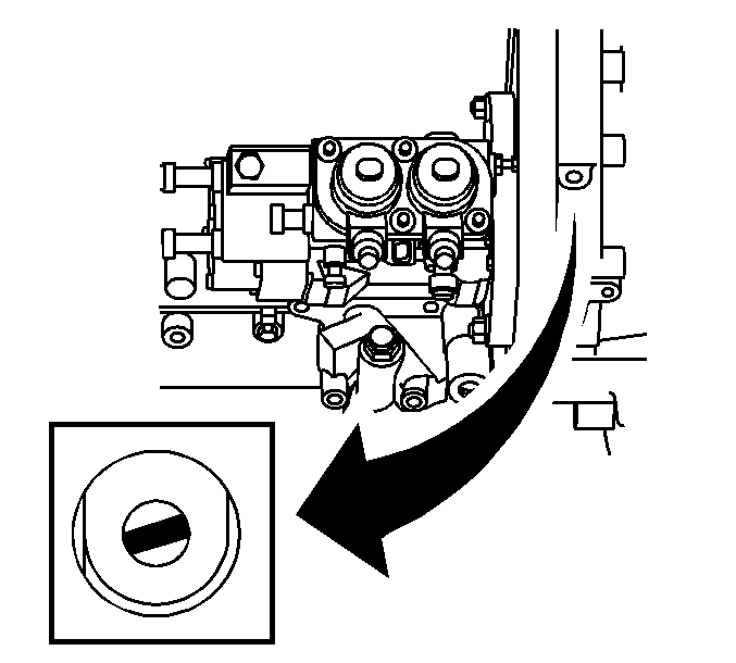
Important: Paint mark must be centered in the inspection hole. If the paint mark is not centered in the inspection hole, the pump must be removed and re-timed.
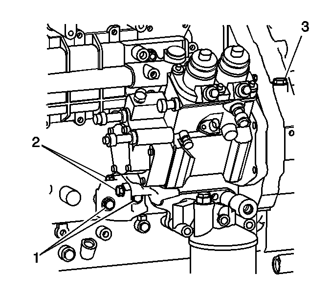
Important: Hand tighten the bolt first, then tighten to specified torque.
Tighten
| • | Bolt (1) to 28.4 N·m (20.9 lb ft) |
| • | Bolt (2) to 56.8 N·m (41.9 lb ft) |
| • | Bolt (3) to 34.3 N·m (25.3 lb ft) |
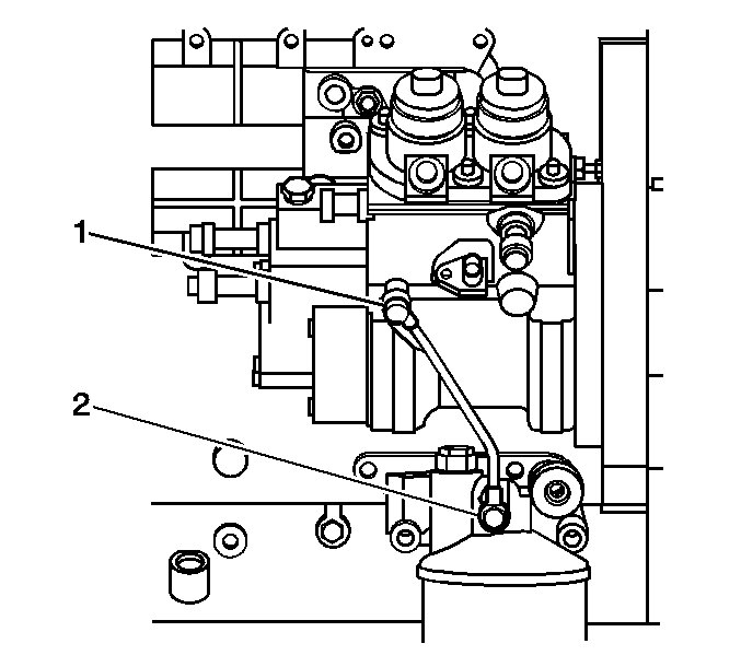
Tighten
| • | Tighten the Eye bolt (1) to 7.9-12.7 N·m (5.8-9.4 lb ft) |
| • | Tighten the Eye bolt (2) to 27.4 N·m (20.2 lb ft) |


Tighten
Tighten the fuel pipe bolts to 44 N·m (33 lb ft).
