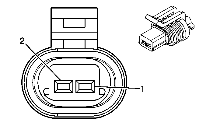
| Table 1: | Brake Fluid Level Switch |
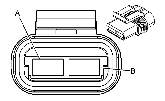
| Table 2: | Hydraulic Brake Inline Fuse |
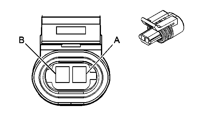
| Table 3: | HYDRO MAX Assembly-C1 |
| Table 4: | HYDRO MAX Assembly-C2 |
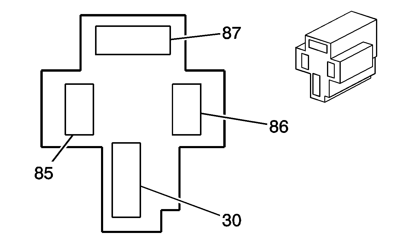
| Table 5: | HYDRO MAX Relay |
| Table 6: | Park Brake Switch (C4/C5) |
| Table 7: | Park Brake Switch (C6/C7/C8) |
| |||||||
|---|---|---|---|---|---|---|---|
Connector Part Information |
| ||||||
Pin | Wire Color | Circuit No. | Function | ||||
1 | BK/WH | 351 | Ground | ||||
2 | PU | 333 | Brake Fluid Level Sensor Signal | ||||
| |||||||
|---|---|---|---|---|---|---|---|
Connector Part Information |
| ||||||
Pin | Wire Color | Circuit No. | Function | ||||
A | OG | 1470 | Brake Booster Pump Motor Supply Voltage | ||||
B | L-GN | 2674 | Battery Positive Voltage | ||||
| |||||||
|---|---|---|---|---|---|---|---|
Connector Part Information |
| ||||||
Pin | Wire Color | Circuit No. | Function | ||||
A | L-BU/BK | 1928 | Brake Booster Fluid Flow Switch Signal | ||||
B | BK | 151 | Ground | ||||

| |||||||
|---|---|---|---|---|---|---|---|
Connector Part Information |
| ||||||
Pin | Wire Color | Circuit No. | Function | ||||
A | OG | 1470 | Brake Booster Pump Motor Supply Voltage | ||||
B | BK | 151 | Ground | ||||
| |||||||
|---|---|---|---|---|---|---|---|
Connector Part Information |
| ||||||
Pin | Wire Color | Circuit No. | Function | ||||
30 | OG | 1470 | Brake Booster Pump Motor Supply Voltage | ||||
85 | TN | 2660 | Extended Travel Brake Switch Signal | ||||
86 | L-BU/BK | 1928 | Brake Booster Fluid Flow Switch Signal | ||||
87 | RD | 2 | Battery Positive Voltage | ||||
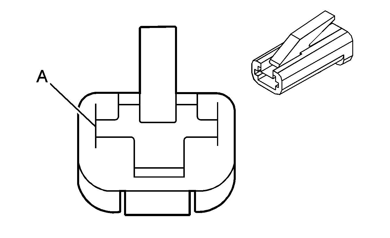
| |||||||
|---|---|---|---|---|---|---|---|
Connector Part Information |
| ||||||
Pin | Wire Color | Circuit No. | Function | ||||
A | L-BU | 1134 | Park Brake Switch Signal | ||||
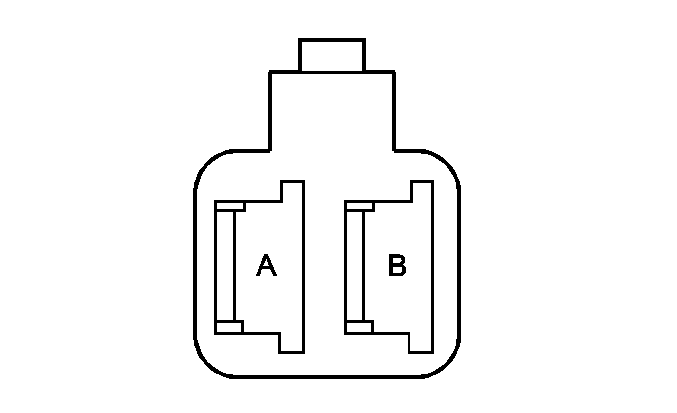
| |||||||
|---|---|---|---|---|---|---|---|
Connector Part Information |
| ||||||
Pin | Wire Color | Circuit No. | Function | ||||
A | L-BU | 1134 | Park Brake Switch Signal | ||||
B | BK | 750 | Ground | ||||
