Steering Knuckle and King Pin Replacement Conventional Wheel Ends
Tools Required
J 8001
Dial Indicator Set
Removal Procedure
- Set the parking brake.
- Block the vehicle rear wheels.
- Raise the front of the vehicle until the tires clear the floor.
- Support the frame using suitable safety stands.
- Remove the tire and wheel assemblies as needed. Refer to
Tire and Wheel Removal and Installation
.
- Remove the hub cap assemblies as needed. Refer to
Hub Cap Replacement
.
- Remove the hub and bearing assemblies. Refer to
Front Wheel Hub, Bearing, and Seal Replacement
.
- Remove the tie rod arms as needed. Refer to
Tie Rod Arm Replacement
.
- Remove the steering arms as needed. Refer to
Steering Arm Replacement
.
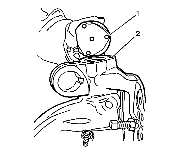
- Remove the cap screws that fasten the king pin caps (1) to the top and bottom of the knuckle (2).
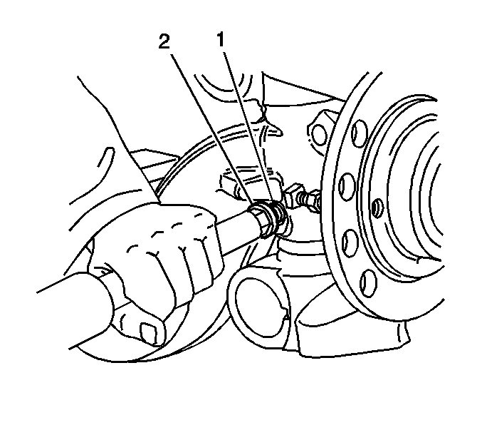
Important: Do not use heat on any parts or fasteners.
- Remove the nut (1) from the draw key (2).
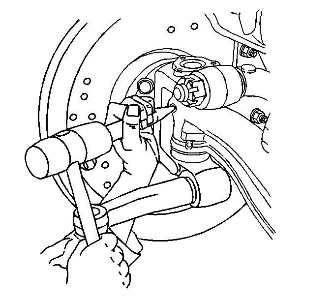
- Remove the draw key from the axle using a hammer and a brass drift.
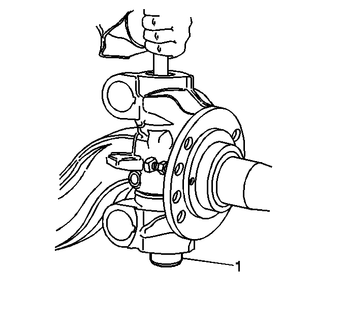
- Remove the king pin (1) by knocking out with a hammer and a brass drift if needed.
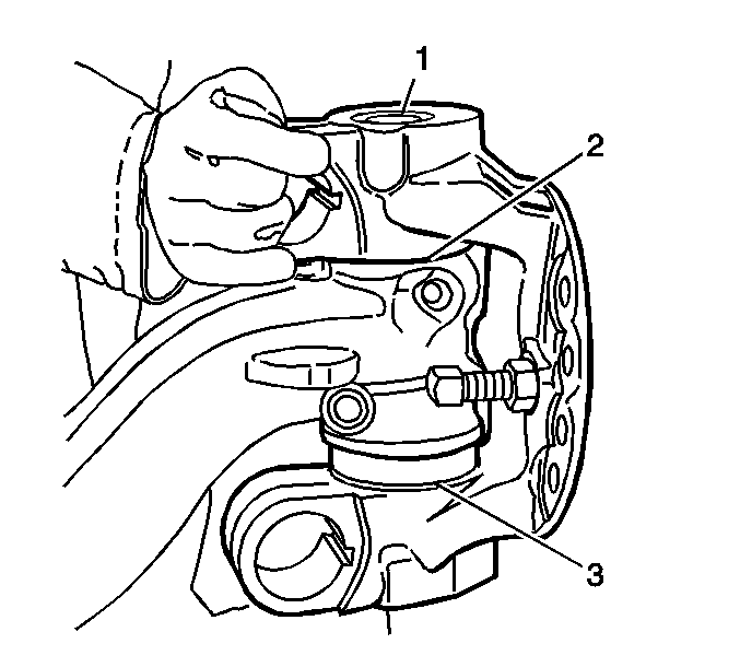
- Remove the steering knuckle (1).
- Remove the following components from the knuckle:
| • | The thrust bearing and seal (3) |
- Discard the thrust bearing (3).
Inspection Procedure
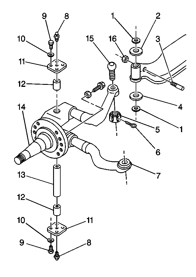
- Clean the axle components using a cleaning solvent.
- Inspect the axle components for the following conditions:
- Use Magna-Flux™ inspection, if available, in order to inspect the steering knuckle (14) and the kingpins (13) for minute cracks, checks, or fractures.
- Inspect the axle king pin (13) bores for the following conditions:
- Inspect the king pin bushing bores for the following conditions:
- Smooth the bore using a crocus cloth or a fine grit sandpaper if needed. Clean the bore.
Installation Procedure
- Install the knuckle (1) to the axle.
- Install the king pin shims (2) and new thrust bearing and seal (3).

- Lightly lubricate the following components:
| • | The thrust bearing areas of the steering knuckle (3) |
| • | The knuckle pin bore of the axle beam (1) |
| • | Pack the bushing bores with grease. |

- Install the knuckle to the axle beam.
- Install pin (1) in knuckle and axle from the top.
- Align the flat of the knuckle pin with the draw key hole.
- Check knuckle vertical play and adjust.
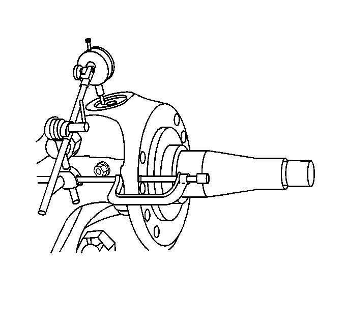
- Check knuckle vertical play using a dial indicator. Reference dial indicator at top of knuckle pin.
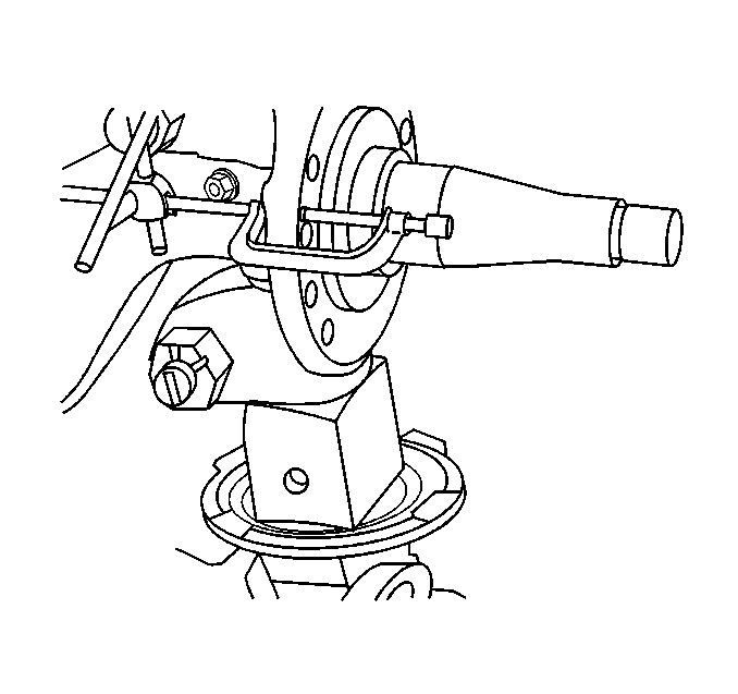
- Simulate axle loading with a jack and note dial indicator reading.
Measure
Knuckle vertical play should be 0.015-0.305 mm (0.002-0.012 in).
- Add or remove shims as necessary to obtain correct vertical end play.

- Install a new draw key.
- Align the draw key hole with the knuckle pin flat.
Notice: Refer to Fastener Notice in the Preface section.

- Install the draw key nut (2).
Tighten
Tighten the nut to 50 N·m (37 lb ft).
Important: Do not apply excessive silicone compound which could block the grease path for the knuckle pin bushings.
- Apply silicone rubber gasket compound to knuckle (2) cap mounting surface.

- Install the knuckle king pin caps (1).
- Install the cap bolts.
Tighten
Tighten the bolts to 35 N·m (26 lb ft).
- Install the steering arms as needed. Refer to
Steering Arm Replacement
.
- Install the tie rod arms as needed. Refer to
Tie Rod Arm Replacement
.
- Install the hub and bearing assemblies. Refer to
Front Wheel Hub, Bearing, and Seal Replacement
.
- Install the hub cap assemblies as needed. Refer to
Hub Cap Replacement
.
- Install the tire and wheel assemblies as needed. Refer to
Tire and Wheel Removal and Installation
.
- Remove the safety stands and lower the vehicle.
- Check the axle alignment.
- Check the stop screw adjustment. Adjust as needed.
Stop Screw Adjustment
Adjust the steering stops so that the power assist stops approximately 3 degrees or 3.175 mm (1/8 in) before reaching the steering stop screws.
Steering Knuckle and King Pin Replacement Unitized Wheel Ends
Tools Required
J 8001
Dial Indicator Set
Removal Procedure
- Set the parking brake.
- Block the vehicle rear wheels. Refer to
Lifting and Jacking the Vehicle
.
- Raise the front of the vehicle until the tires clear the floor.
- Support the frame using suitable safety stands.
- Remove the tire and wheel assemblies as needed. Refer to
Tire and Wheel Removal and Installation
.
- Remove the hub cap assemblies as needed. Refer to
Hub Cap Replacement
.
- Remove the hub and bearing assemblies. Refer to
Front Wheel Hub, Bearing, and Seal Replacement
.
- Remove the tie rod arms as needed. Refer to
Tie Rod Arm Replacement
.
- Remove the steering arms as needed. Refer to
Steering Arm Replacement
.
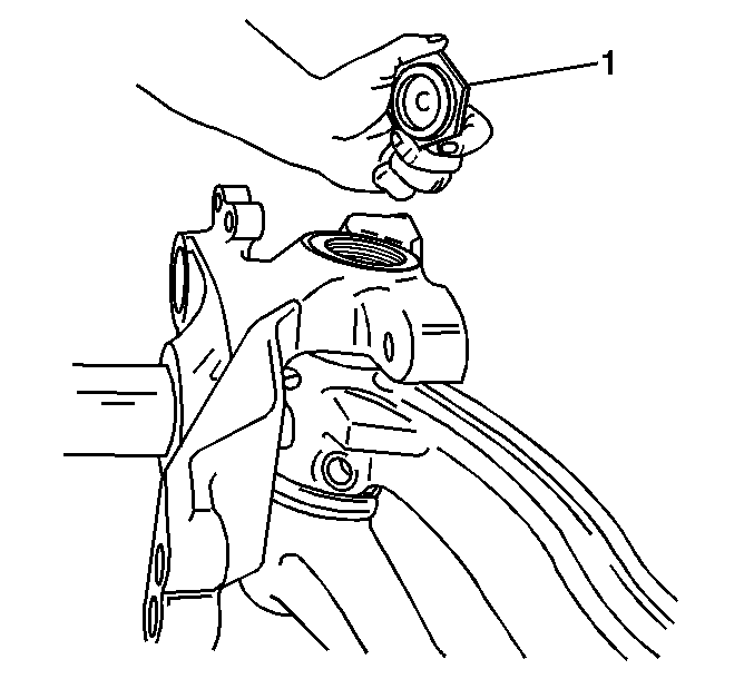
- Remove the king pin caps (1) from the top and bottom of the knuckle.
Important: Do not use heat on any parts or fasteners.
- Remove the draw key as follows:
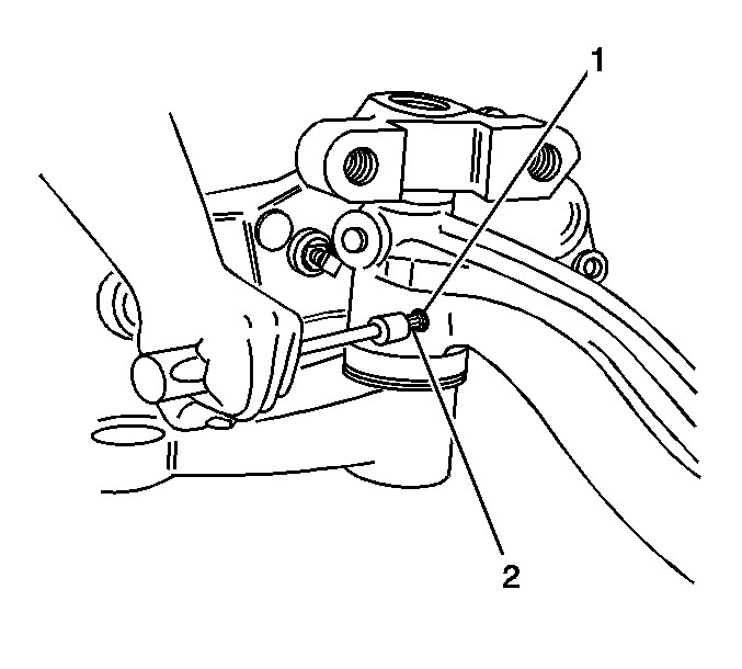
- Remove nut (2) from the draw key (1).
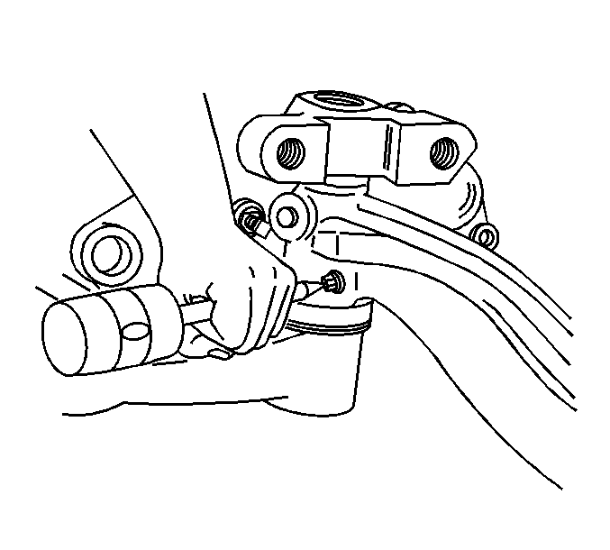
- Remove the draw key from the axle using a hammer and a brass drift.
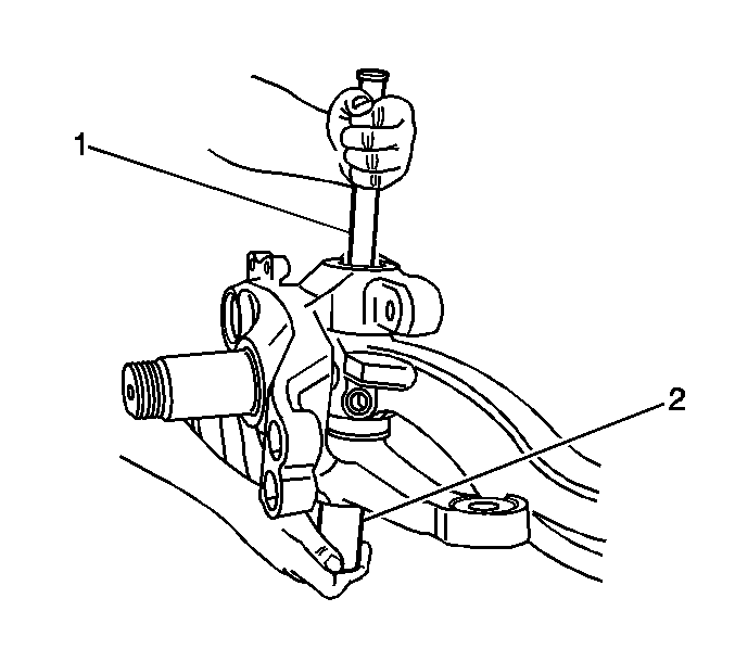
- Remove the king pin (2) by knocking out with a hammer and a brass drift (1) if needed.
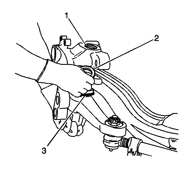
- Remove the following components from the knuckle:
| • | The thrust bearing and seal (3) |
- Discard the thrust bearing (3).
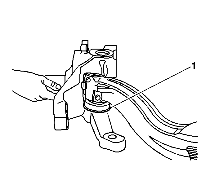
- Remove the knuckle (1) assembly.
Inspection Procedure

- Clean the axle components using a cleaning solvent.
- Inspect the axle components for the following conditions:
- Use Magna-Flux™ inspection, if available, in order to inspect the steering knuckle (14) and the kingpins (13) for minute cracks, checks, or fractures.
- Inspect the axle king pin (13) bores for the following conditions:
- Inspect the king pin bushing bores for the following conditions:
- Smooth the bore using a crocus cloth or a fine grit sandpaper if needed. Clean the bore.
Installation Procedure

- Install the knuckle (1) to the axle.
- Install the king pin shims (2) and new thrust bearing and seal (3).

- Lightly lubricate the following components:
| • | The thrust bearing areas of the steering knuckle |
| • | The knuckle pin bore of the axle beam |
| • | Pack the bushing bores with grease. |

- Install the knuckle to the axle beam.
- Install the pin (2) in the knuckle and the axle from the top.
- Align the flat of the knuckle pin with the draw key hole.
- Check the knuckle vertical play and adjust.

- Check the knuckle vertical play using a dial indicator. Reference the dial indicator at the top of the knuckle pin.

- Simulate axle loading with a jack and note the dial indicator reading.
Measure
Knuckle vertical play should be 0.015-0.305 mm (0.002-0.012 in).
- Add or remove shims as necessary to obtain correct vertical end play.

- Install a new draw key.
- Align the draw key hole with the knuckle pin flat.
Notice: Refer to Fastener Notice in the Preface section.

- Install draw key nut (2).
Tighten
Tighten the nut to 50 N·m (37 lb ft).
Important: Do not apply excessive silicone compound which could block the grease path for the knuckle pin bushings.
- Apply silicone rubber gasket compound to knuckle cap mounting surface.

- Install the knuckle king pin caps (1).
- Install the cap bolts.
Tighten
Tighten the bolts to 35 N·m (26 lb ft).
- Install the steering arms as needed. Refer to
Steering Arm Replacement
.
- Install the tie rod arms as needed. Refer to
Tie Rod Arm Replacement
.
- Install the hub and bearing assemblies. Refer to
Front Wheel Hub, Bearing, and Seal Replacement
.
- Install the hub cap assemblies as needed. Refer to
Hub Cap Replacement
.
- Install the tire and wheel assemblies as needed. Refer to
Tire and Wheel Removal and Installation
.
- Remove the safety stands and lower the vehicle.
- Check the axle alignment.
- Check the stop screw adjustment. Adjust as needed.
Stop Screw Adjustment
Adjust the steering stops so that the power assist stops approximately 3 degrees or 3.175 mm (1/8 in) before reaching the steering stop screws.


