Tools Required
| • | J 23907 Slide
Hammer with Bearing Adapter |
| • | J 36825 Output
Shaft Oil Seal Remover - 4WD Models Only |
| • | J 44725 Gear
Pack Assembly Fixture |
| • | J 44730 Intermediate
Case Puller Legs |
- Remove the drain plug
and drain the transmission fluid.
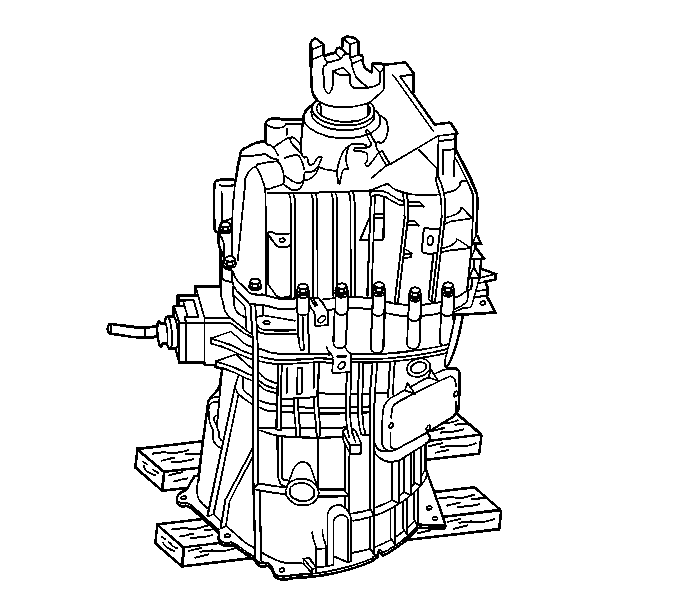
- Position the transmission
on the floor with the output shaft up. Use boards in order to allow for the
protrusion of the input shaft.
- If the transmission is equipped with a power take-off (PTO),
remove the PTO.
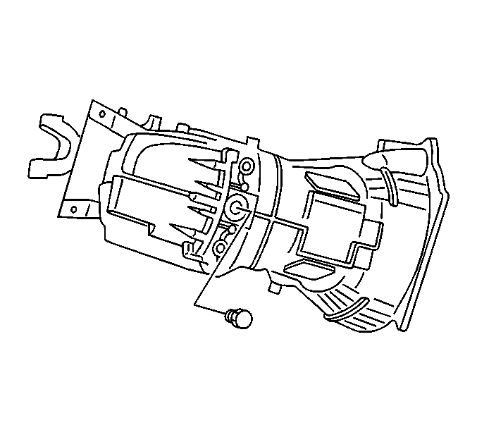
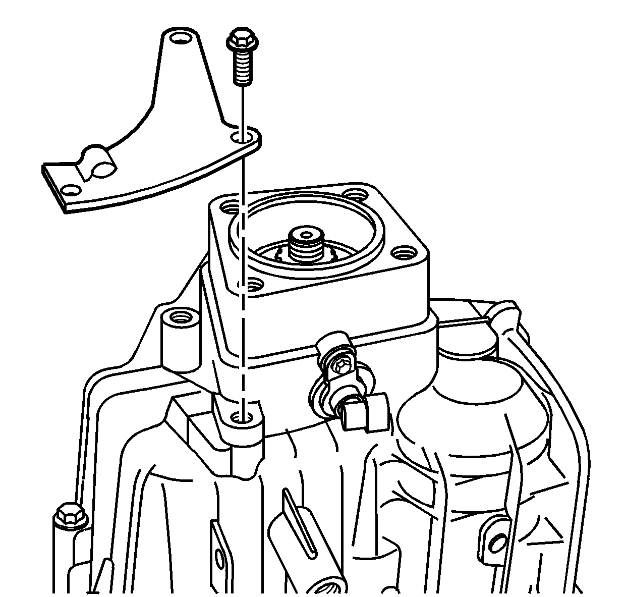
- Remove the shift control
housing bolts.
- Remove the shift control housing assembly.
- For RWD transmission,
using the J 8614-01
, loosen
the propeller shaft yoke nut.
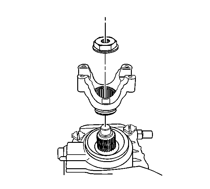
- For RWD transmission,
remove the propeller shaft yoke nut and discard.
- Remove the propeller shaft yoke.
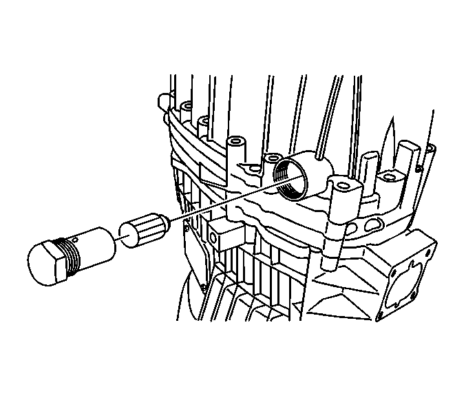
- Remove the shift shaft
detent sleeve and the shift shaft detent plunger.
Notice: Do not nick, scratch or damage the sealing surface. The
sealing surface is a machined surface. Damage to the machined surface can
cause leakage.
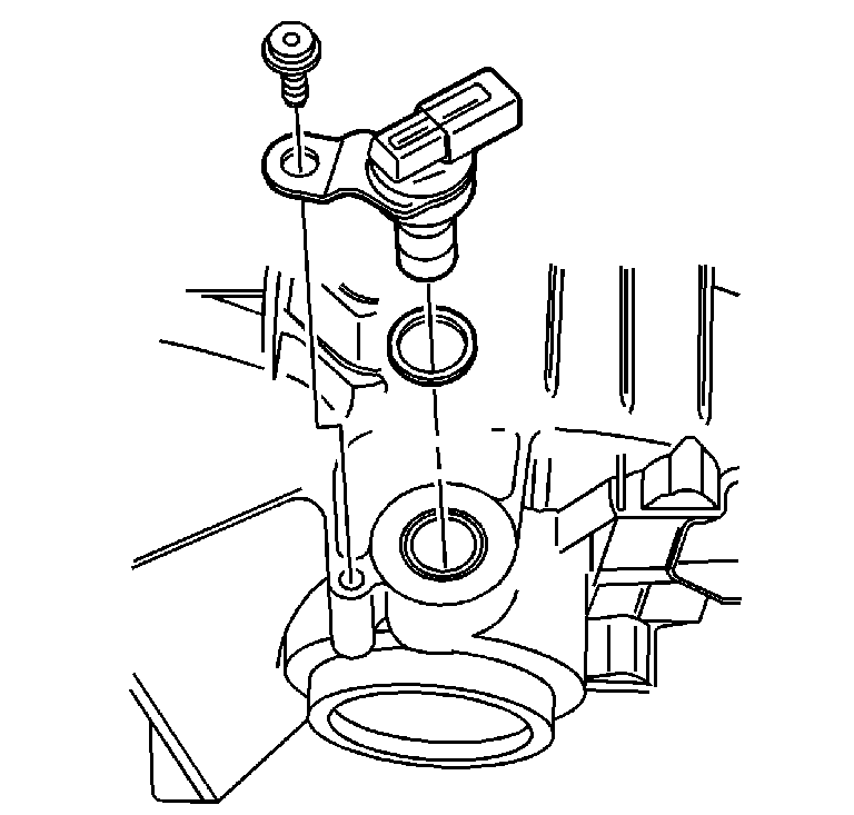
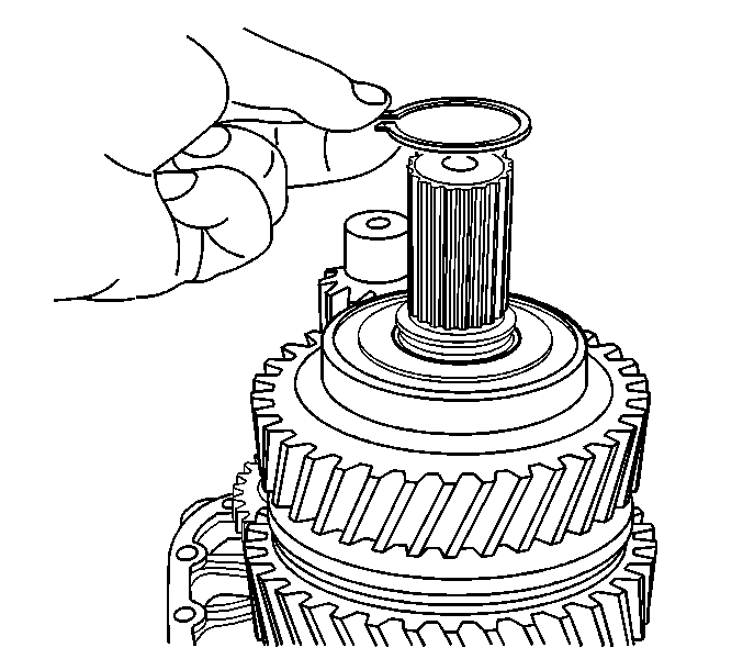
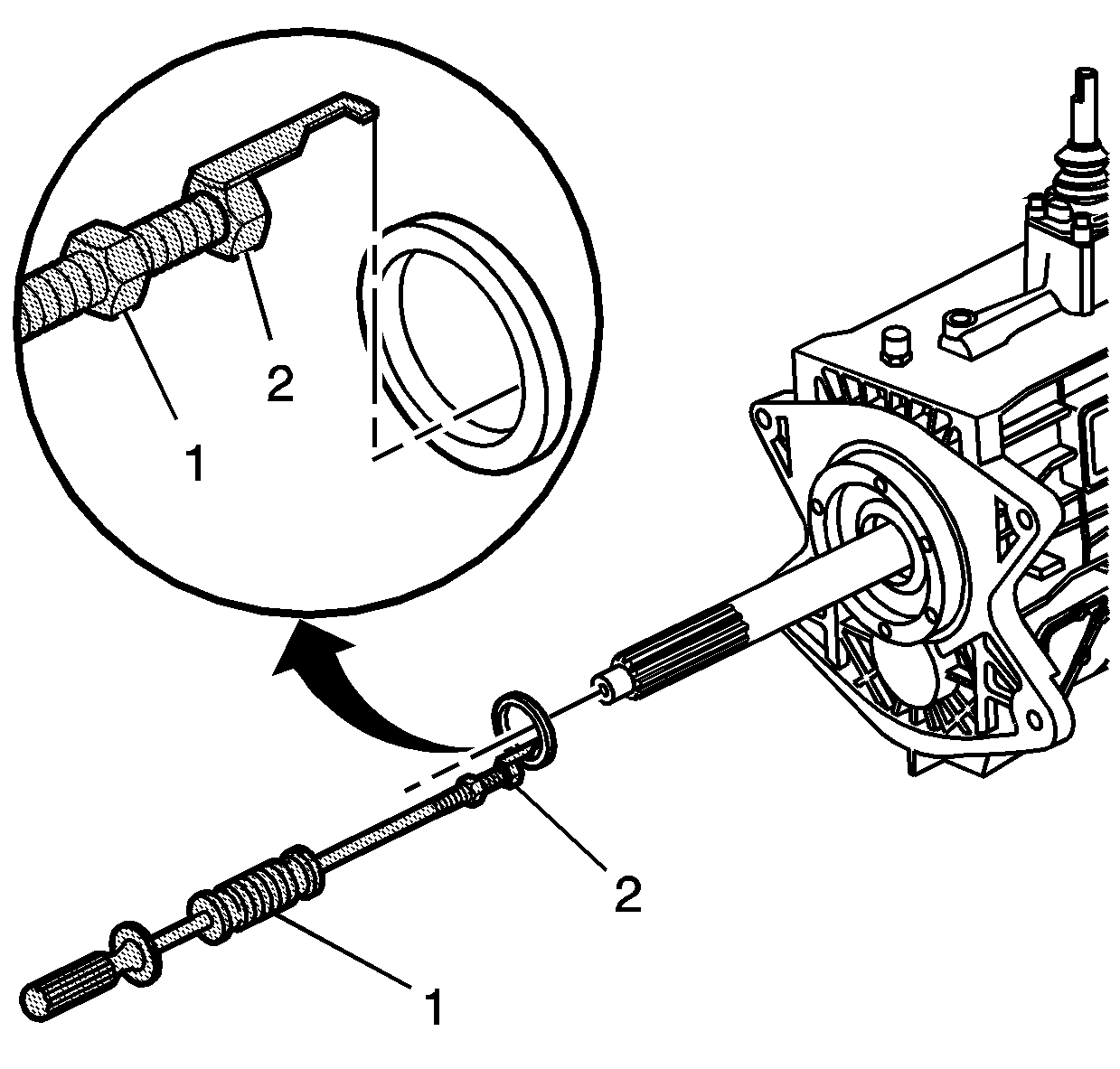
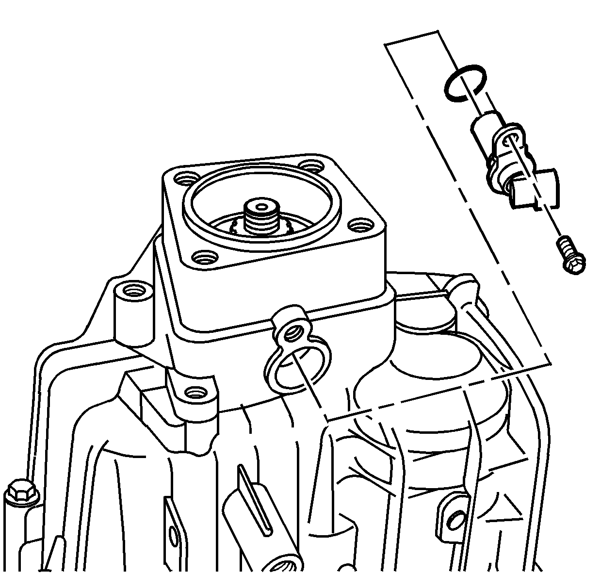
- If RWD, remove the vehicle speed sensor (VSS) bolt and washer.
- Remove the VSS and O-ring seal.
- Remove and discard the O-ring seal.
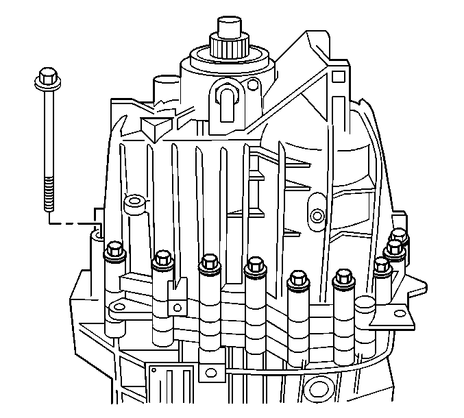
- Remove the 19 bolts
retaining the rear case to the front case.
Important: Do not separate the rear case from the intermediate case by using a
pry bar between the cases. The cases have machined sealing surfaces.
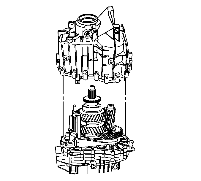
- Remove the rear case.
| • | Use a soft-face hammer and hit up on the rear case. |
| • | The cases should come apart once the sealer is broken. |
| • | There are 2 dowel pins that may bind in the rear case. |
| • | The mainshaft rear bearing is a slip fit in the rear case and
may bind if the case is not lifted up straight. |
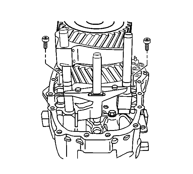
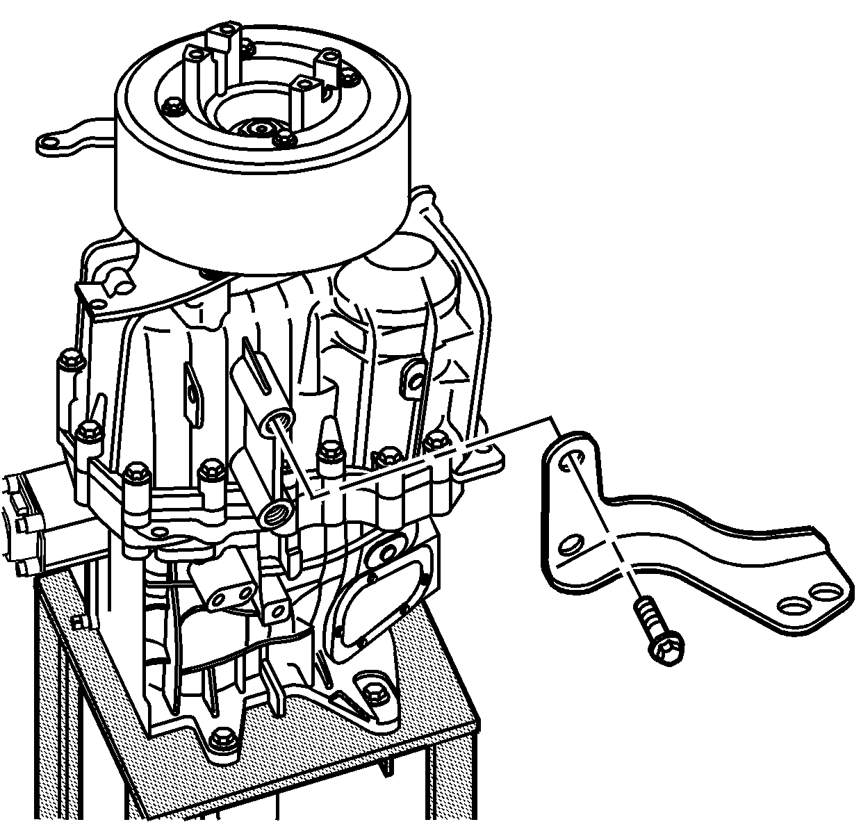
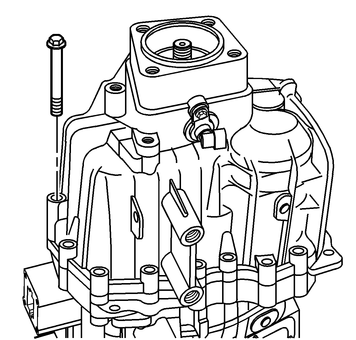
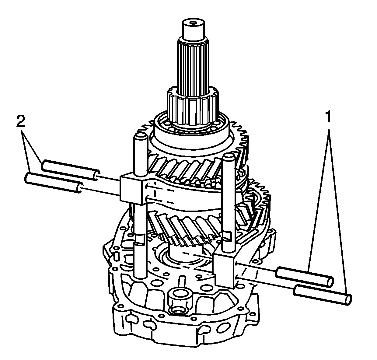
- Remove the 2 bolts
for the intermediate case.
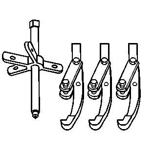
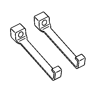
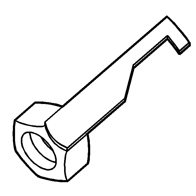
- Install the S-hooks
in the webbing of the intermediate case to the locations shown.
Attach a suitable chain to the S-hooks.
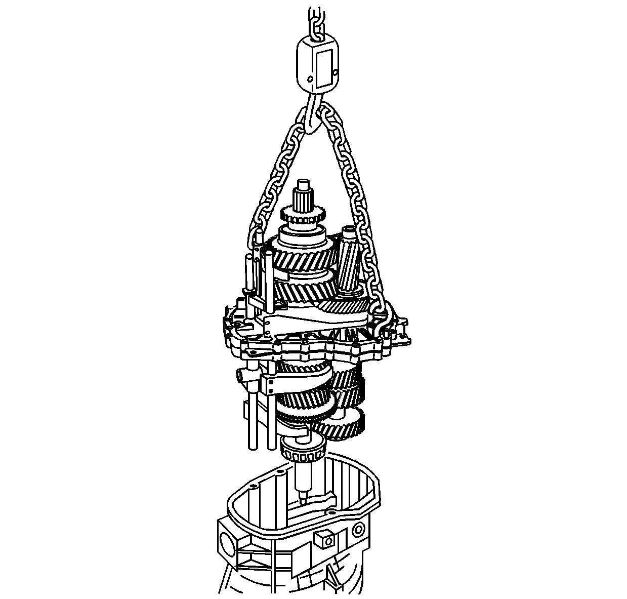
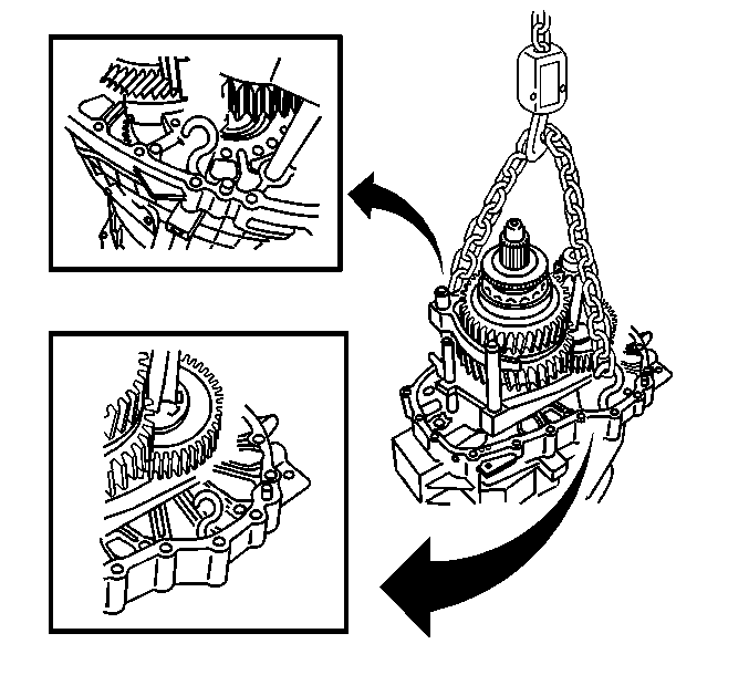
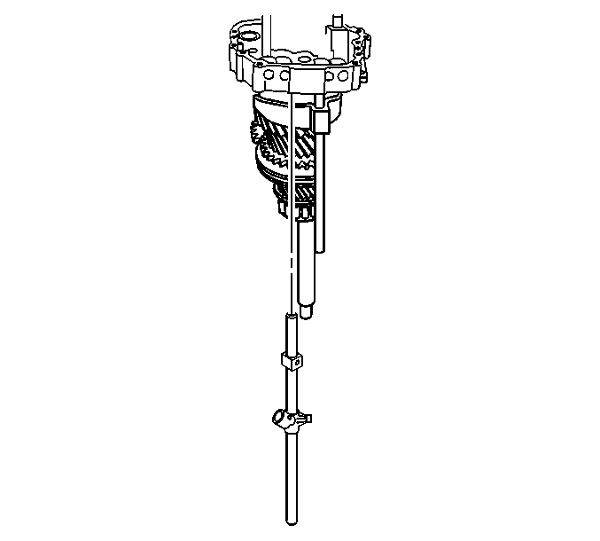
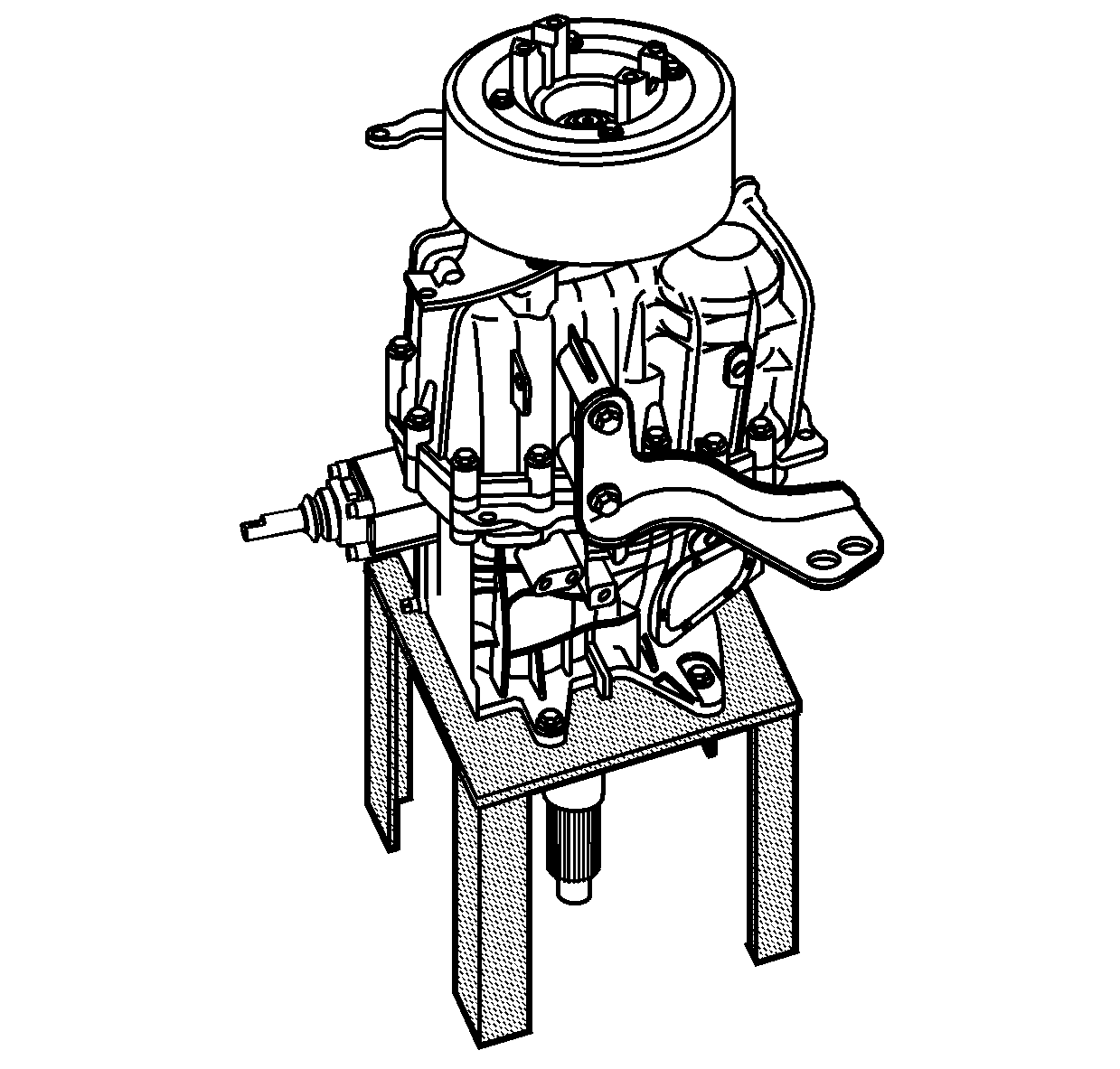
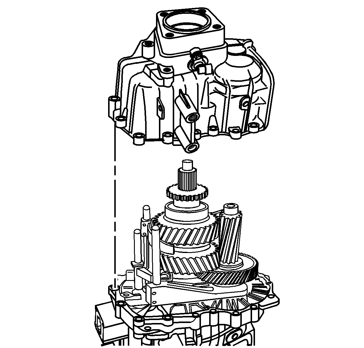
- Using a suitable lifting
device, carefully remove the gear assembly from the front case.
Important: The weight of the gear assembly is extended over the edge of the workbench.
The weight may tip over or overload a standard metal workbench.
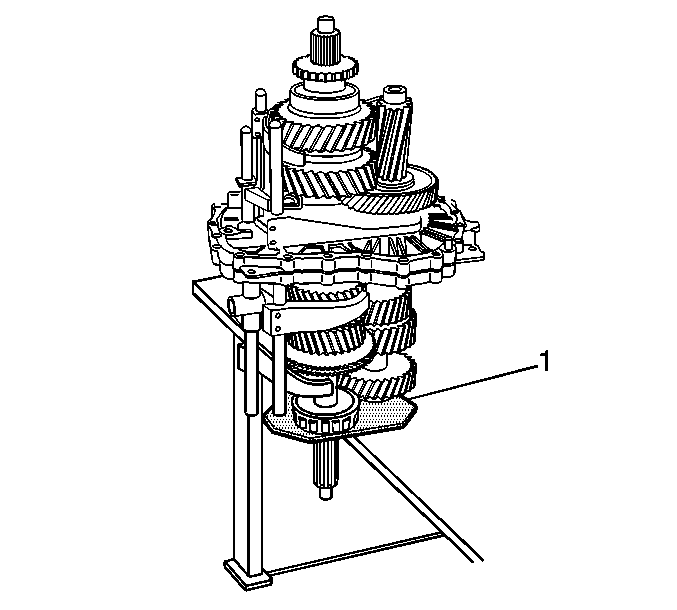
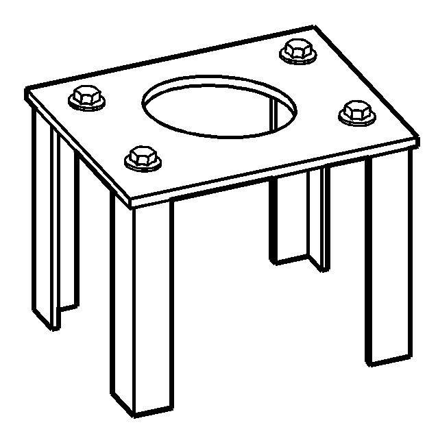
- Secure the J 44725
(1)
to a sturdy workbench.
- Position the gear assembly on the J 44725
.
Notice: When removing the roll pins from the shift shafts use a punch that is
a slightly smaller diameter than the roll pin. Flaring of the shift shaft
groove may occur if the punch binds. This will result in extra effort
to remove the shift forks or shift control levers. When double roll pins
are used, remove both of the roll pins at the same time. Support the shift
component when removing the roll pins to prevent damage to the shift shafts.
Do not reuse the roll pins after removal.
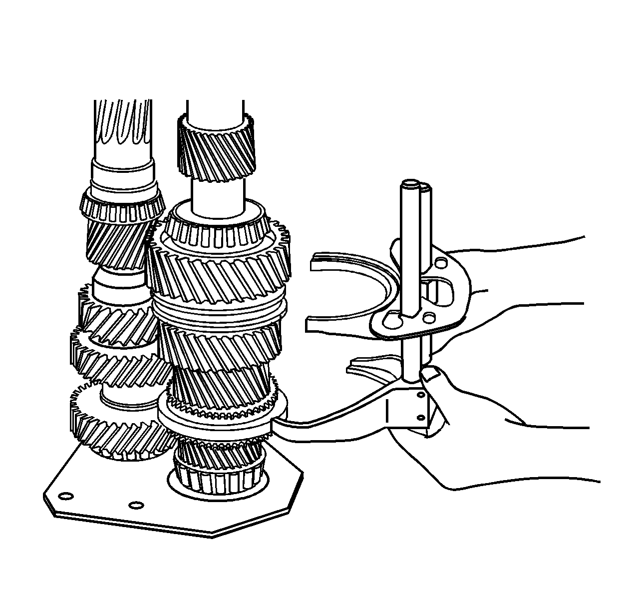
- Using a hammer and punch, remove the roll pins from the
internal shift control rear lever.
- Remove the internal shift
control rear lever.
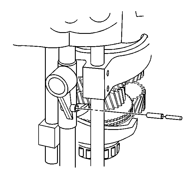
- Using a hammer and a punch,
remove the roll pins for the internal shift control front lever.
- Remove the internal shift
control front lever.
| 23.1. | Turn the internal shift control front lever in order to clear
the 2nd/3rd shift fork and the 4th/5th shift fork. |
| 23.2. | Remove the shift shaft with the internal shift control front lever. |
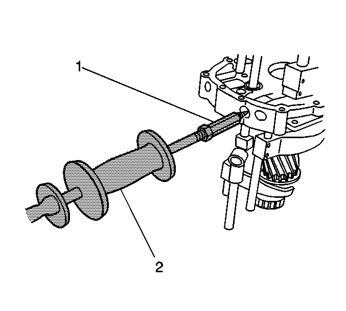
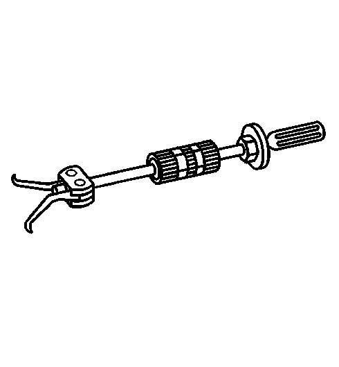
- Using the J 36825
(1) and the J 23907
(2), remove the 4 shift
shaft detent plugs.
Important: Only remove the plungers as needed for replacement.
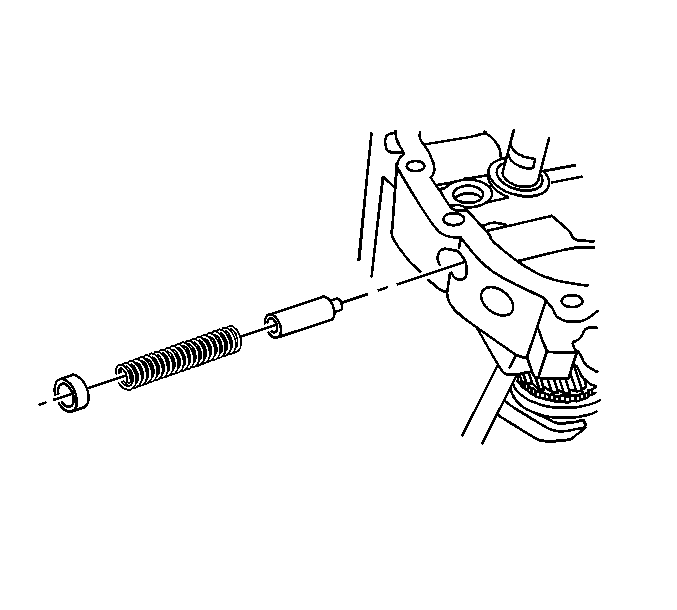
- Remove the shift shaft detent springs and the shift shaft detent plungers.
The plungers should only be removed if replacing the plungers. The plungers
may be hard to come out now. After removing the shift shafts, the plungers
will be easier to remove.
Notice: When removing the roll pins from the shift shafts use a punch that is
a slightly smaller diameter than the roll pin. Flaring of the shift shaft
groove may occur if the punch binds. This will result in extra effort
to remove the shift forks or shift control levers. When double roll pins
are used, remove both of the roll pins at the same time. Support the shift
component when removing the roll pins to prevent damage to the shift shafts.
Do not reuse the roll pins after removal.
Important: The 4th/5th shift fork and the 2nd/3rd shift fork do not require removal
from the shift shafts for transmission disassembly. Do not remove the roll
pins from the 4th/5th shift fork and the 2nd/3rd shift fork unless replacing
the shift forks or the shift shafts.
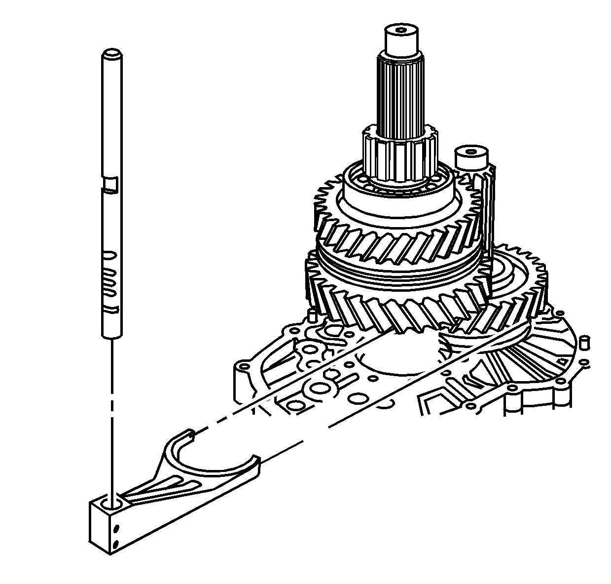
- Remove the following roll pins:
| • | The 6th gear shift fork (1) |
| • | The 1st/reverse gear shift fork (2) |
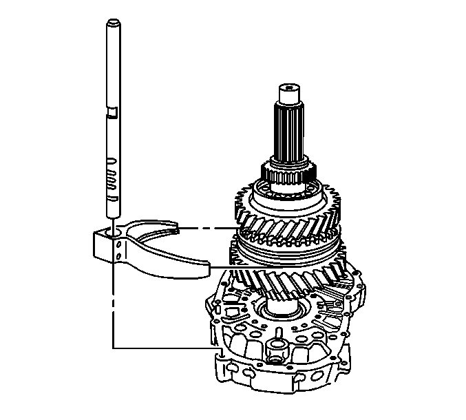
- Remove the 6th gear shift
fork and shaft.
| 27.1. | Move the interlock plate in the 6th gear position by moving the
plate toward the 1st/reverse shift shaft. |
| 27.2. | Pull up on the shift shaft while tapping down on the shift fork
with a soft-face hammer. |
| 27.3. | Remove the shift fork and shaft from the 6th gear synchronizer
assembly. |
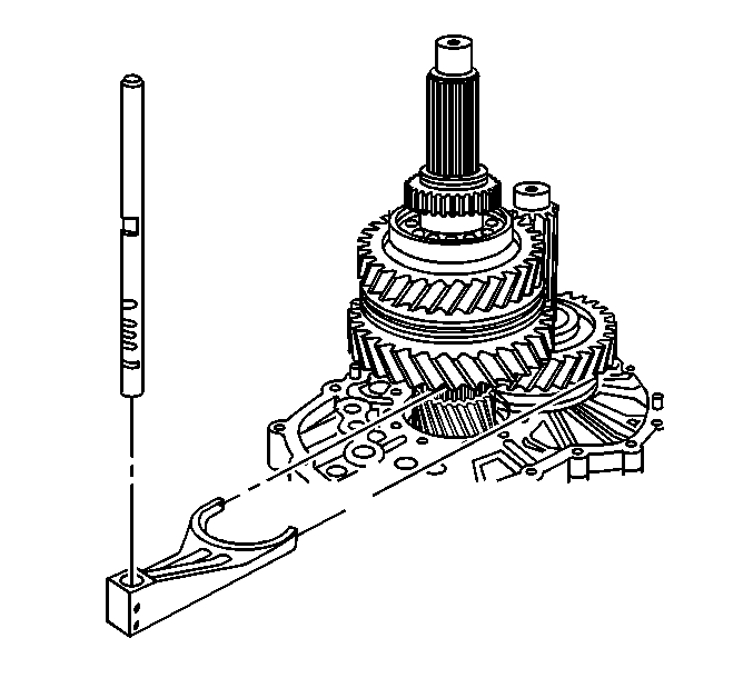
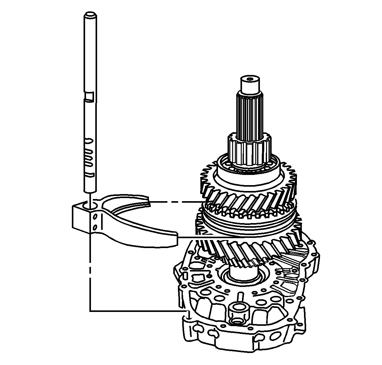
- Remove the 1st/reverse
shift fork and shaft.
| 28.1. | Move the interlock plate in the reverse gear shift position by
moving the plate toward the 6th gear shift shaft. |
| 28.2. | Pull up on the shift shaft while tapping down on the shift fork
with a soft-face hammer. |
| 28.3. | Remove the shift fork and shaft from the 1st/reverse gear synchronizer
hub. |
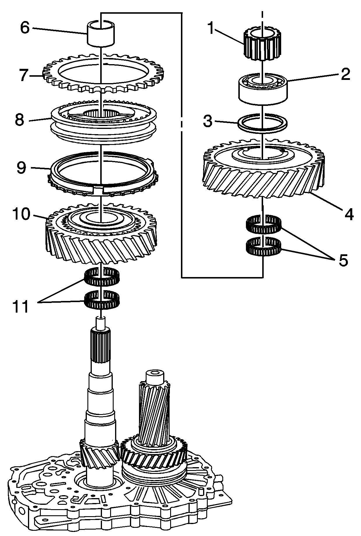
- If 4WD, remove the retaining
ring for the mainshaft rear bearing.
- Using the J 44726
, remove the gears from the mainshaft.
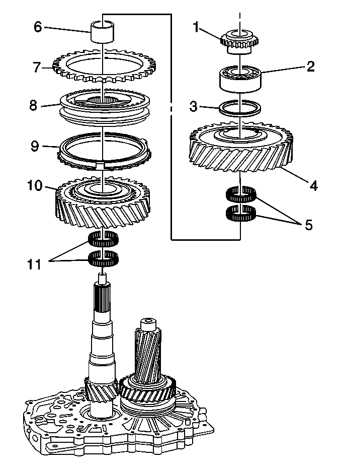
- Remove the following components
from the mainshaft:
| 31.1. | The speed sensor reluctor wheel, RWD only (1) |
| 31.2. | The mainshaft rear bearing (2) |
| 31.3. | The reverse gear thrust washer (3) |
| 31.4. | The reverse gear (4) |
| 31.5. | The reverse gear bearings (5) |
| 31.6. | The reverse gear bushing (6) |
| 31.7. | The reverse gear synchronizer blocking ring (7) |
| 31.8. | The 1st/reverse synchronizer assembly (8) |
| 31.9. | The 1st gear synchronizer blocking ring (9) |
| 31.11. | The 1st gear bearings (11) |
- Remove the retaining ring
for the 6th gear.
- Remove the following components
from the countershaft (4):
| 33.1. | The thrust washer (1) |
| 33.3. | The 6th gear bearing (3) |
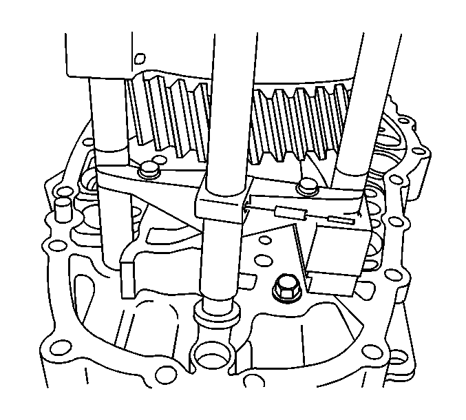
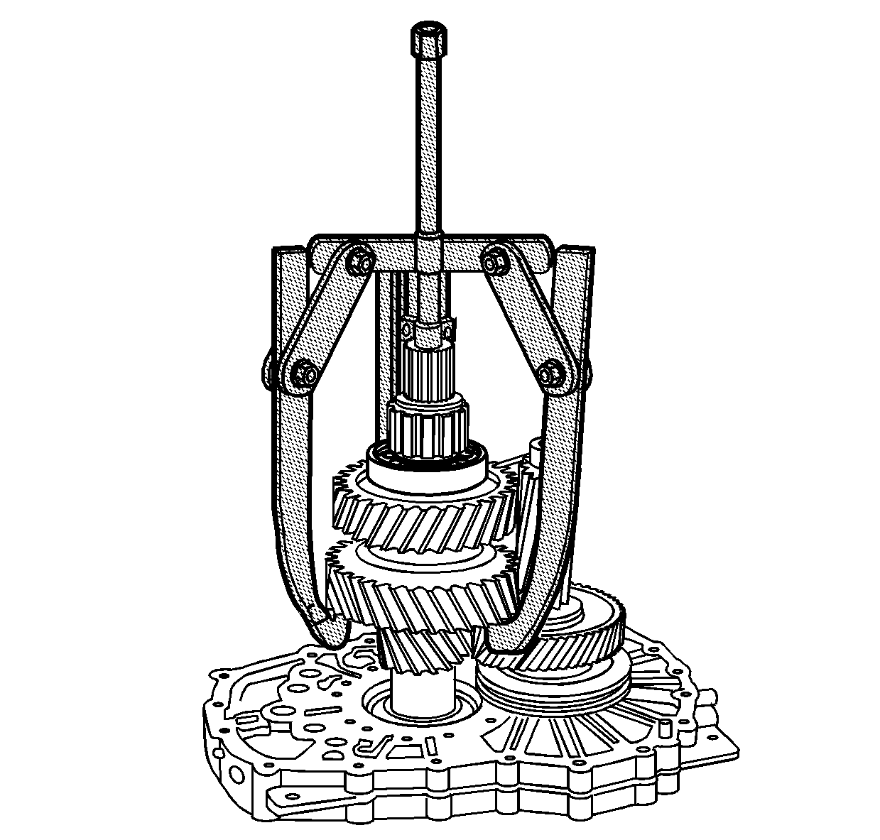
- Remove the bolts for the
shift interlock plate.
- Let the shift interlock plate rest on the shift shafts.
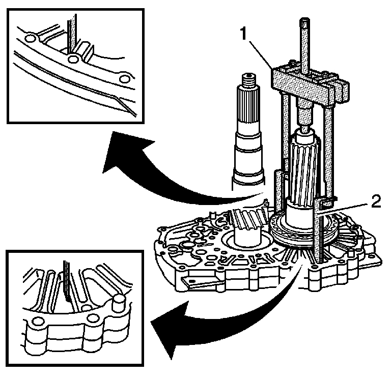
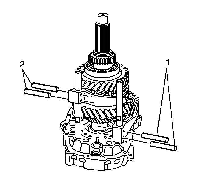
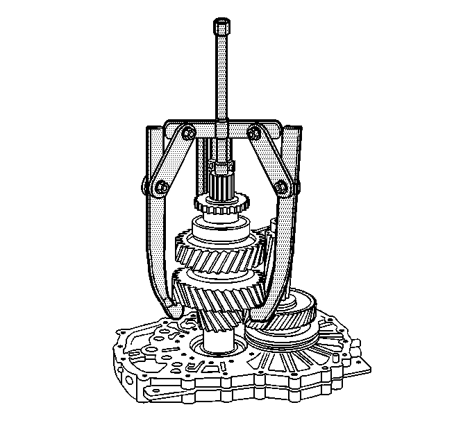
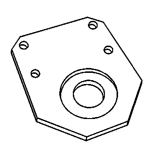
- Install the J 44730
(2) to the J 44707
(1).
Important: You will be using the intermediate case to pull off the 6th gear synchronizer
hub and the 6th gear bushing. Ensure the J 44730
is properly located on the intermediate case.
- Install the J 44730
(2)
on the intermediate case as shown. The J 44730
needs to be aligned in order for the J 44707
to be centered on the mainshaft.
- Using the J 44730
(2) and the J 44707
(1) on the countershaft, remove the 6th gear synchronizer
hub and 6th gear bushing.
| • | The intermediate case will slide off the 2nd/3rd shift shaft and
the 4th/5th shift shaft. |
| • | Keep the shift shafts straight in order to ensure the intermediate
case does not bind on the shift shafts. |
| • | If the intermediate case starts to bind on the shift shafts, stop
pulling. |
| • | Straighten the shift shafts in the intermediate case and continue
pulling. |
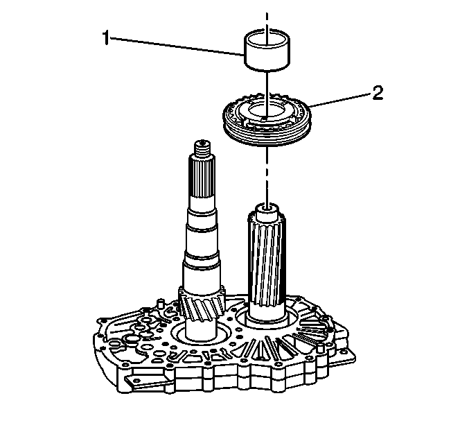
- Remove the 6th gear bearing
race (1).
- Remove the 6th gear synchronizer assembly (2).
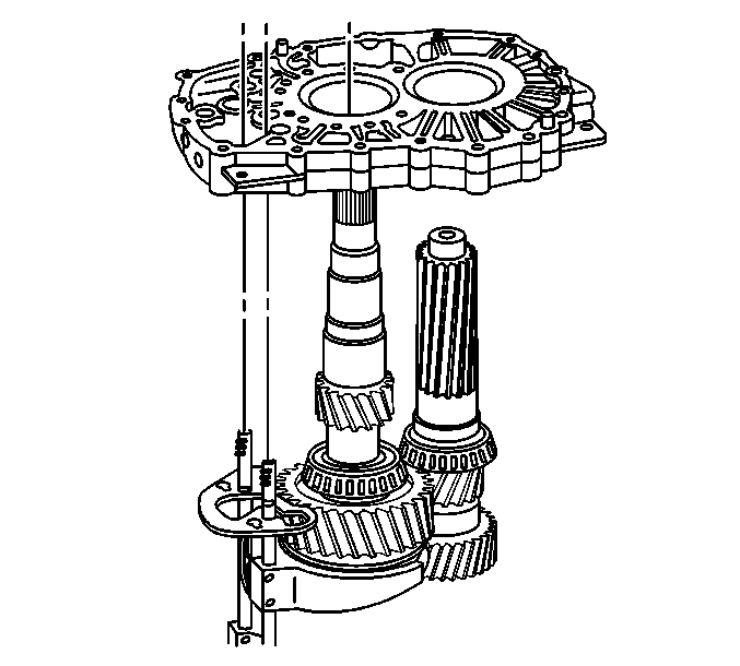
- Remove the intermediate
case from the mainshaft and the countershaft.
- Remove the 6th gear spacer
from the countershaft.
- Remove the 2nd/3rd shift
fork and shaft, the 4th/5th shift fork and shaft, and the shift interlock
plate from the mainshaft assembly.
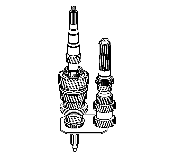
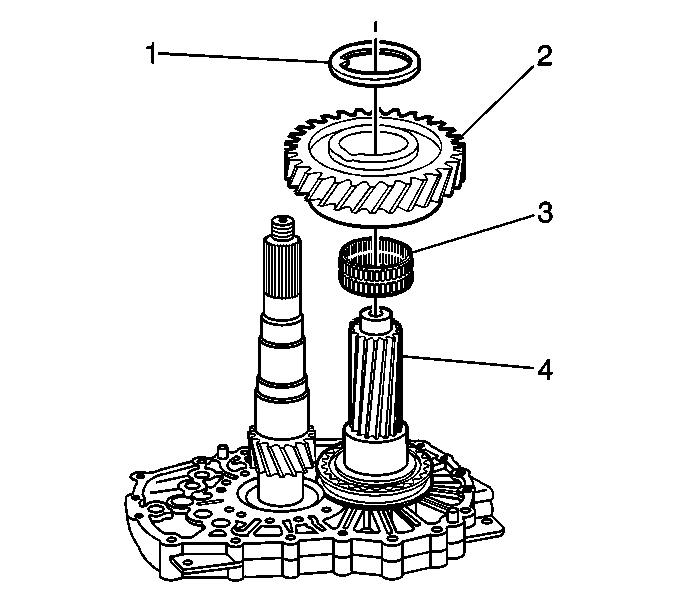
- Remove the countershaft
from the mainshaft by walking the countershaft away.
Tools Required
| • | J 36825 Output
Shaft Oil Seal Remover - 4WD Models Only |
| • | J 44725 Gear
Pack Assembly Fixture |
| • | J 44730 Intermediate
Case Puller Legs |
Important: The ZF S6-650 manual transmission is used with 4 different
applications, depending on the engine or if equipped with the driveline parking
brake. The disassemble procedures are the same for all 4 applications,
except where indicated.
The 4 different applications are as follows:
| • | 8.2L engine with driveline parking brake - uses 1480 series size
yoke and 4 bolt hole park brake drum |
| • | 8.2L engine without driveline parking brake - uses 1480 series
size yoke |
| • | 6.6L engine with driveline parking brake - uses 1550 series size
yoke and 8 bolt hole park brake drum |
| • | 6.6L engine without driveline parking brake - uses 1550 series
size yoke |
- Remove the drain plug and drain the transmission fluid. Ensure all of
the fluid is drained.
- If the transmission is equipped with a power take-off (PTO),
remove the PTO.
- Remove the 6 bolts
holding the quill tube to the front of the transmission.
- Remove the quill tube.
- Using the J 23907
(1) and the J 45278
(2), remove the input shaft
seal.
- Install the J 45279
to the front of the transmission.
- Tip the transmission up on the J 45279
.
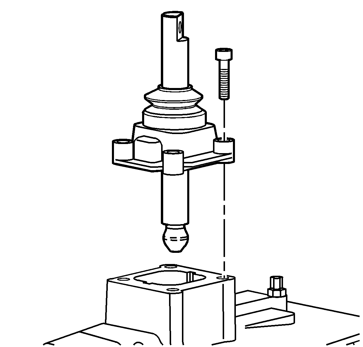
- Remove the shift control
housing bolts.
- Remove the shift control housing assembly.
- Remove the clutch cable
bracket bolts and the bracket.
- Using the J 8614-01
, loosen the propeller shaft yoke
nut. Use 2 3/8 NF bolts to hold the J 8614-01
to the propeller shaft yoke.
Important:
| • | If equipped, the parking brake drum does not require removal from the
propeller shaft yoke for transmission disassembly or assembly. |
| • | If removing the parking brake drum, and then reusing the drum, the
drum to yoke requires alignment mark for assembling. The original drum and
yoke come as a balanced assembly. |
- Remove the propeller shaft yoke nut and discard.
- Remove the parking brake
drum/yoke assembly or the yoke flange.
- If equipped, remove the
bolts retaining the parking brake shoe bracket to the rear case.
- If equipped, remove, as an assembly, the parking brake shoes,
bracket, and cam lever.
- If equipped, remove the
bolts retaining the parking brake cable bracket.
- If equipped, remove the parking brake cable bracket.
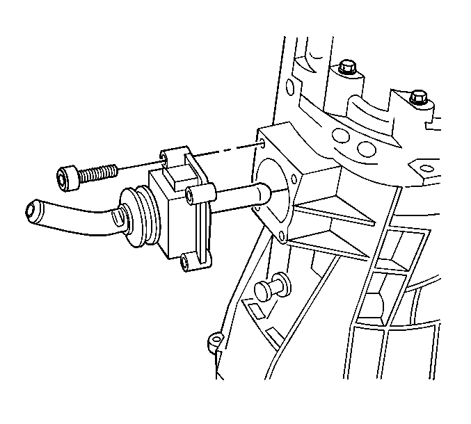
- Remove the bolt retaining
the vehicle speed sensor (VSS).
- Remove the VSS and the O-ring seal.
- Remove and discard the O-ring seal.
- Remove the shift shaft
detent sleeve and the shift shaft detent plunger.
- Remove the 19 bolts
retaining the rear case to the front case.
Notice: Refer to Machined Surface Damage Notice in the Preface section.
Important: Do not separate the rear case from the intermediate case by using a
pry bar between the cases.
- Remove the rear case.
| • | Use a soft-face hammer and hit up on the rear case. |
| • | The cases should come apart once the sealer is broken. |
| • | There are 2 location pins that may bind in the rear case. |
| • | The mainshaft rear bearing is a slip fit in the rear case and
may bind if the case is not lifted up straight. |
- Remove the 2 bolts
for the intermediate case.
- Install the S-hooks in
the webbing of the intermediate case to the locations shown.
Attach a suitable chain to the S-hooks.
- Using a suitable lifting
device, carefully remove the gear assembly from the front case.
Important: The weight of the gear assembly is extended over the edge of the workbench.
The weight may tip over or overload a standard metal work bench.
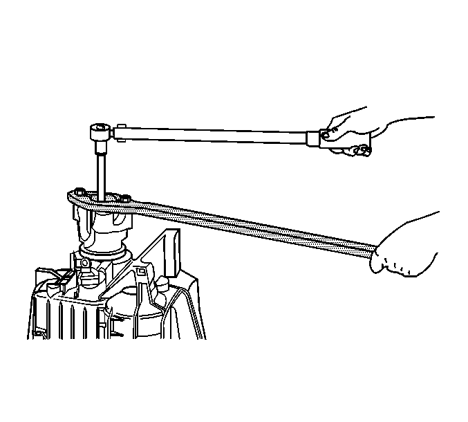
- Secure the J 44725
(1)
to a sturdy workbench.
- Position the gear assembly on the J 44725
.
Notice: When removing the roll pins from the shift shafts use a punch that is
a slightly smaller diameter than the roll pin. Flaring of the shift shaft
groove may occur if the punch binds. This will result in extra effort
to remove the shift forks or shift control levers. When double roll pins
are used, remove both of the roll pins at the same time. Support the shift
component when removing the roll pins to prevent damage to the shift shafts.
Do not reuse the roll pins after removal.
- Using a hammer and punch, remove the roll pins from the
internal shift control rear lever.
- Remove the internal shift
control rear lever.
- Using a hammer and a punch,
remove the roll pins for the internal shift control front lever.
- Remove the internal shift
control front lever.
| 32.1. | Turn the internal shift control front lever in order to clear
the 2nd/3rd shift fork and the 4th/5th shift fork. |
| 32.2. | Remove the shift shaft with the internal shift control front lever. |
- Using the J 36825
(1) and the J 23907
(2), remove the 4 shift
shaft detent plugs.
Important: Only remove the plungers as needed, for replacement.
- Remove the shift shaft detent springs and the shift shaft detent plungers.
The plungers should only be removed if replacing the plungers. The plungers
may be hard to come out now. After removing the shift shafts, the plungers
will be easier to remove.
Notice: When removing the roll pins from the shift shafts use a punch that is
a slightly smaller diameter than the roll pin. Flaring of the shift shaft
groove may occur if the punch binds. This will result in extra effort
to remove the shift forks or shift control levers. When double roll pins
are used, remove both of the roll pins at the same time. Support the shift
component when removing the roll pins to prevent damage to the shift shafts.
Do not reuse the roll pins after removal.
Important: The 4th/5th shift fork and the 2nd/3rd shift fork do not require removal
from the shift shafts for transmission disassembly. Do not remove the roll
pins from the 4th/5th shift fork and the 2nd/3rd shift fork unless replacing
the shift forks or the shift shafts.
- Remove the following roll pins:
| • | The 6th gear shift fork (1) |
| • | The 1st/reverse gear shift fork (2) |
- Remove the 6th gear
shift fork and shaft.
| 36.1. | Move the interlock plate in the 6th gear position by moving
the plate towards the 1st/reverse shift shaft. |
| 36.2. | Pull up on the shift shaft while tapping down on the shift fork
with a soft-faced hammer. |
| 36.3. | Remove the shift fork and shaft from the 6th gear synchronizer
assembly. |
- Remove the 1st/reverse
shift fork and shaft.
| 37.1. | Move the interlock plate in the reverse gear shift position by
moving the plate towards the 6th gear shift shaft. |
| 37.2. | Pull up on the shift shaft while tapping down on the shift fork
with a soft-faced hammer. |
| 37.3. | Remove the shift fork and shaft from the 1st/reverse gear synchronizer
hub. |
- Using the J 44726
, remove the gears from the mainshaft.
- Remove the following components
from the mainshaft:
| 39.1. | The speed sensor reluctor wheel (1) |
| 39.2. | The mainshaft rear bearing (2) |
| 39.3. | The reverse gear thrust washer (3) |
| 39.4. | The reverse gear (4) |
| 39.5. | The reverse gear bearings (5) |
| 39.6. | The reverse gear bushing (6) |
| 39.7. | The reverse gear synchronizer blocking ring (7) |
| 39.8. | The 1st/reverse synchronizer assembly (8) |
| 39.9. | The 1st gear synchronizer blocking ring (9) |
| 39.11. | The 1st gear bearings (11) |
- Remove the retaining ring
for the 6th gear.
- Remove the following components
from the countershaft (4):
| 41.1. | The thrust washer (1) |
| 41.3. | The 6th gear bearing (3) |
- Remove the bolts for the
shift interlock plate.
- Let the shift interlock plate rest on the shift shafts.
- Install the J 44730
(2) to the J 44707
(1).
Important: Use the intermediate case to pull off the 6th gear synchronizer
hub and the 6th gear bushing. Ensure the J 44730
is properly located on the intermediate case.
- Install the J 44730
(2)
on the intermediate case as shown. The J 44730
needs to be aligned in order for the J 44707
to be centered on the mainshaft.
- Using the J 44730
(2) and the J 44707
(1) on the countershaft, remove the 6th gear synchronizer
hub and 6th gear bushing.
| • | The intermediate case will slide off the 2nd/3rd shift
shaft and the 4th/5th shift shaft. |
| • | Keep the shift shafts straight to ensure the intermediate case
does not bind on the shift shafts. |
| • | If the intermediate case starts to bind on the shift shafts, stop
pulling. |
| • | Straighten the shift shafts in the intermediate case again, and
continue pulling. |
- Remove the 6th gear
bearing race (1).
- Remove the 6th gear synchronizer assembly (2).
- Remove the intermediate
case from the mainshaft and the countershaft.
- Remove the 6th gear
spacer from the countershaft.
- Remove the 2nd/3rd shift
fork and shaft, the 4th/5th shift fork and shaft, and the shift interlock
plate from the mainshaft assembly.
- Remove the countershaft
from the mainshaft by walking the countershaft away.
