For 1990-2009 cars only
Parking Brake Shoe Replacement 9 x 3
Warning: Refer to Brake Dust Warning in the Preface section.
Removal Procedure
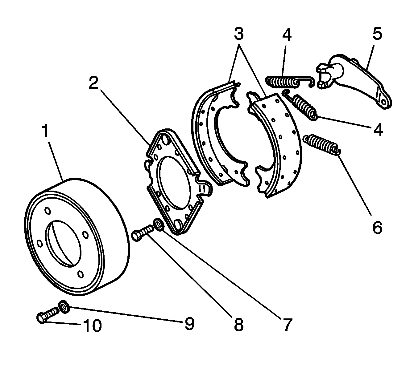
- Remove the drum (1). Refer to Propeller Shaft Parking Brake Drum Replacement.
- Remove the return springs (3, 6).
- Remove the parking brake support plate (2).
- Remove the linings (3).
- Inspect the linings for contamination.
- Inspect the linings for excessive wear. The minimum lining thickness is 1.52 mm (0.60 in).
- Replace the linings, if necessary.
- Inspect the return springs (3) and the anchor spring (6). The return springs and the anchor spring should not have a loss of tension or openings in the coils.
- Replace the return springs (4) and the anchor spring (6) , if necessary.
- Inspect the shoe webs where there is contact with the camshaft (5) and park brake support plate (2).
- Replace the linings if the shoe webs are severely worn.
- Inspect the support plate for damage, distortion and corrosion.
- Remove corrosion from the contact surfaces with a fine emery cloth.
- Replace the support plate if there is damage or distortion.

Always replace the linings as a set.
Installation Procedure
- Apply a thin coat of GM P/N 1051344 (Canadian P/N 993037) or equivalent to the surface of the support plate and the support plate guides.
- Install the anchor spring (6).
- Move the anchor ends of the linings together in order to overlap the shoe webs.
- Install one lining on the guides of the support plate (2).
- Lubricate the anchor pins where the anchor pins contact the shoe webs with GM P/N 1051344 (Canadian P/N 993037) or equivalent.
- Install the second lining.
- Install the return springs (4).
- Install the drum (1). Refer to Propeller Shaft Parking Brake Drum Replacement.
- Adjust the parking brake. Refer to Parking Brake Adjustment.

Parking Brake Shoe Replacement 12 x 3
Warning: Refer to Brake Dust Warning in the Preface section.
Removal Procedure
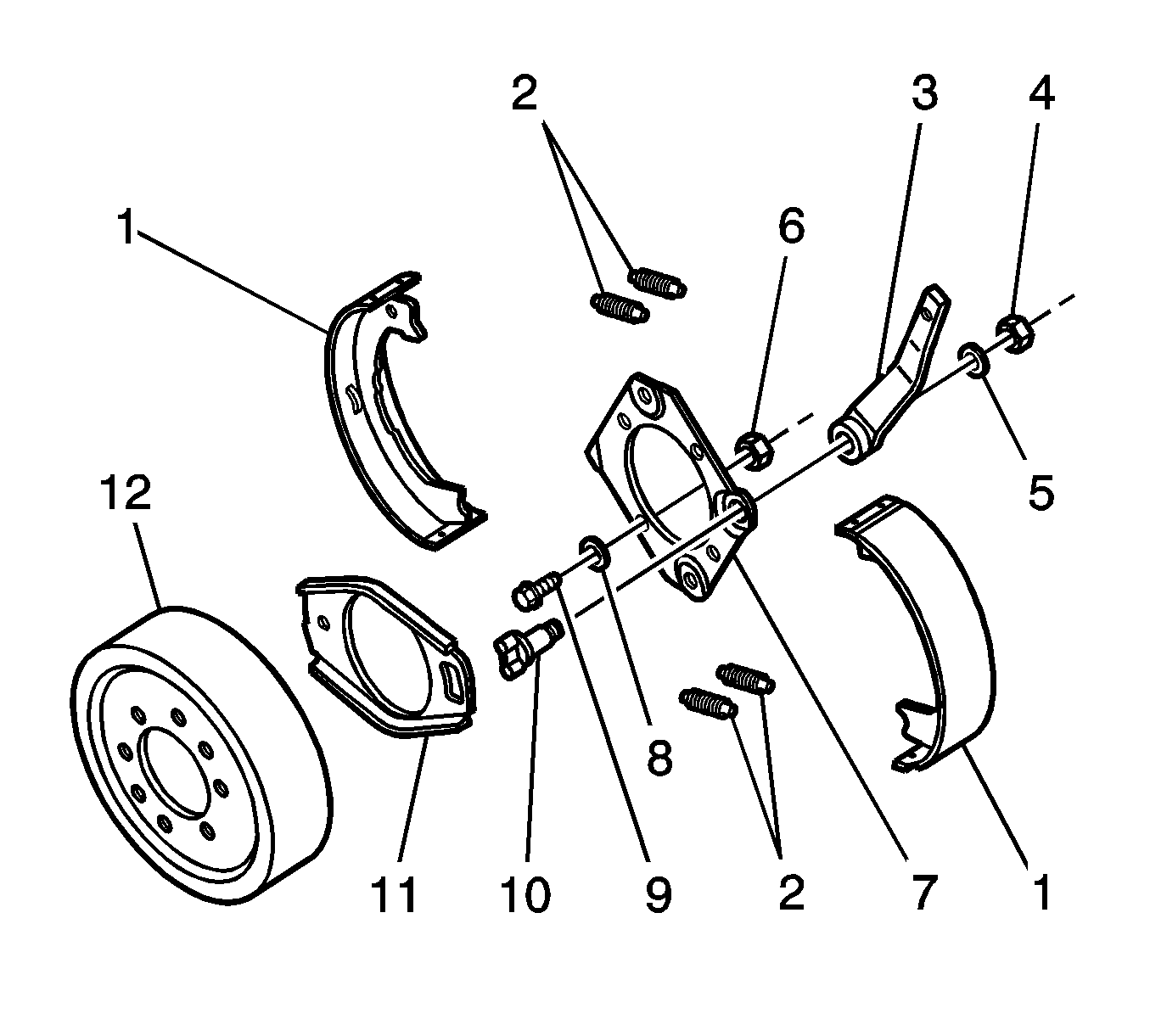
- Remove the drum (12). Refer to Propeller Shaft Parking Brake Drum Replacement.
- Remove the return springs (2).
- Remove the linings (1).
- Inspect the linings for contamination.
- Inspect the linings for excessive wear. The minimum thickness with bonded linings is 1.52 mm (0.60 in).
- Replace the linings (1) as a set, if necessary.
- Inspect the springs (2) for distortion.
- Replace the springs, if necessary.
- Inspect the cam lever 3 and strut (11) for grooves at the brake shoe contact points.
- Replace the cam and strut (11) lever if necessary.

Installation Procedure
- Install the linings.
- Place the cam lever (10) and strut (11) in position with the contact points between the shoe webs.
- Use GM P/N 1051344 (Canadian P/N 993037) or equivalent in order to lubricate the points where the brake shoes contact the support plate.
- Install the return springs (2).
- Install the drum (12). Refer to Propeller Shaft Parking Brake Drum Replacement.
- Adjust the parking brake. Refer to Parking Brake Adjustment.

Parking Brake Shoe Replacement J69
Removal Procedure
Warning: Refer to Brake Dust Warning in the Preface section.
- Raise and support the vehicle. Refer to Lifting and Jacking the Vehicle.
- Remove the tire and the wheel. Refer to Tire and Wheel Removal and Installation.
- Disable the park brake cable automatic adjuster.
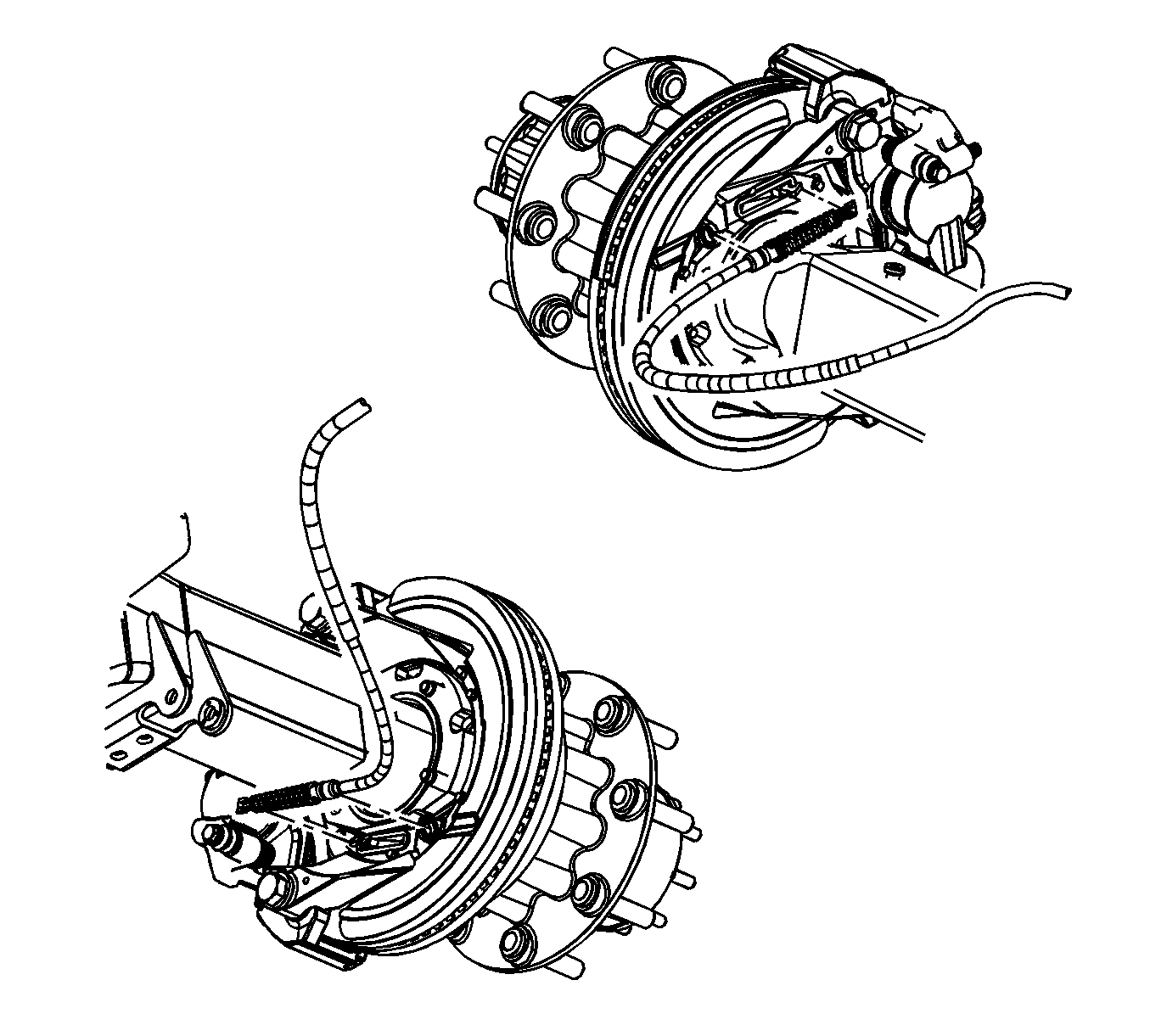
- Remove the park brake cable from the park brake actuator lever.
- Remove the rotor. Refer to Rear Brake Rotor Replacement.
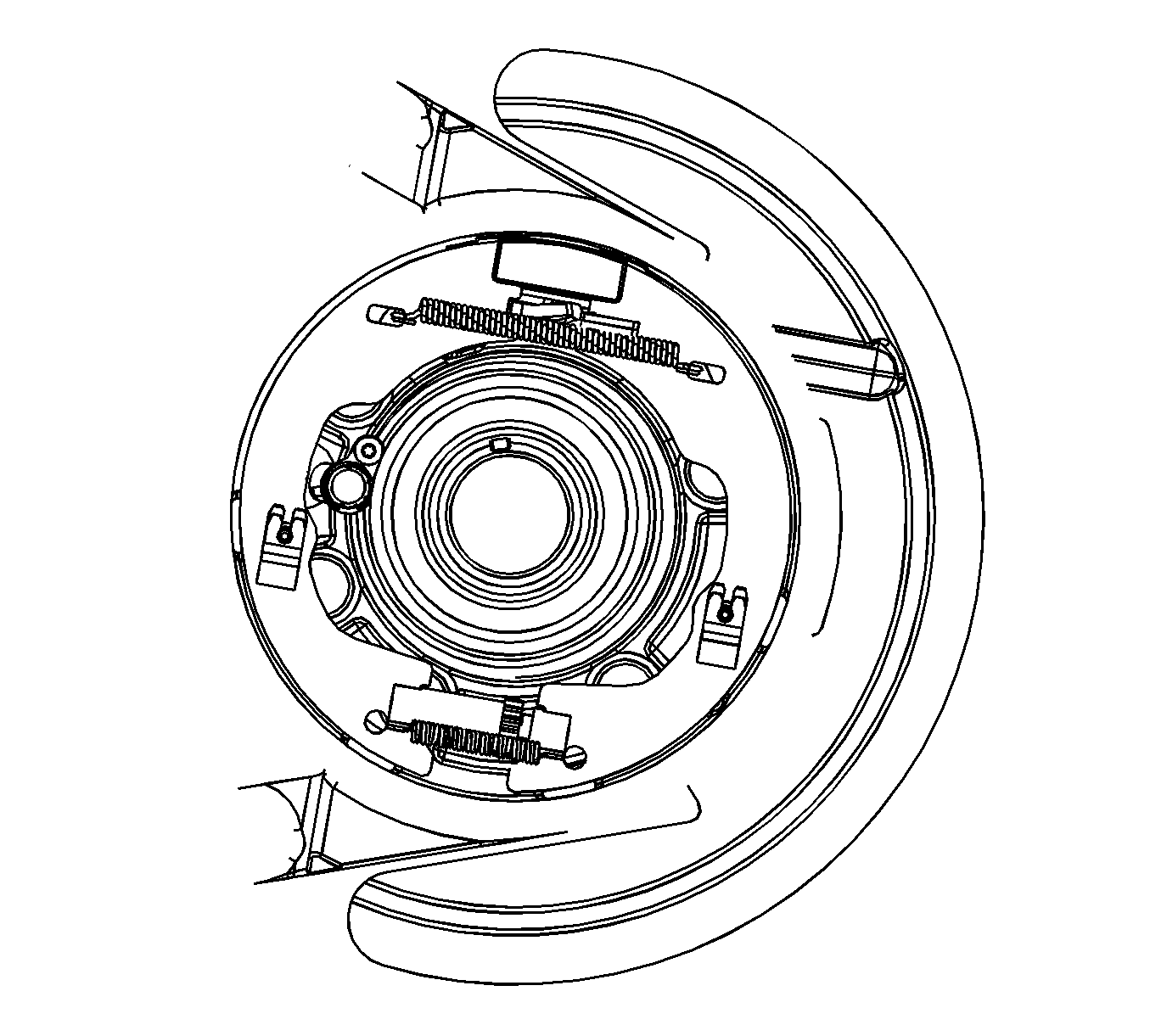
- Turn the adjustment screw to the fully home position in the notched adjustment nut.
- Remove the park brake shoe assembly from the backing plate by removing the tips from the slots and sliding the shoe towards the retaining spring until the shoe disengages from the spring.
- Remove the park brake shoe assembly from the vehicle by placing one of the open ends of the shoe over the axle flange and rotating the shoe until it has cleared the flange.


Installation Procedure
- Clean the debris and the dust from the park brake components using a clean shop cloth.
- Align the slots in both the adjusting screw and tappet to be parallel with the backing plate face.
- Install the park brake shoe assembly to the vehicle by placing one of the open ends of the shoe over the axle flange and rotating the shoe until it is behind the flange.
- Position the park brake shoe on the inboard side of the actuator.
- Slide the park brake shoe into position and seat into the retaining spring.
- Inspect the shoe assembly position.
- Install the park brake cable to the actuator lever.
- Install the rotor. Refer to Rear Brake Rotor Replacement.
- Install the tire and wheel. Refer to Tire and Wheel Removal and Installation.
- Remove the safety stands.
- Lower the vehicle.
- Adjust park brake cable. Refer to Parking Brake Adjustment.


