Tools Required
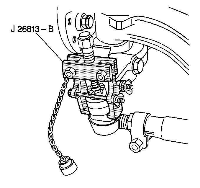
J 26813-B Steering Linkage Puller
Removal Procedure
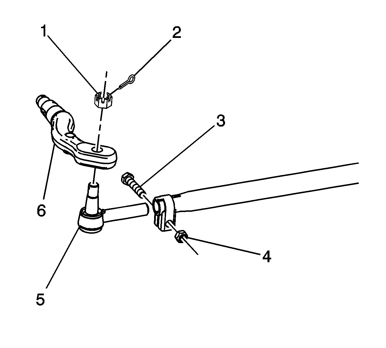
- Remove the cotter pin (2) from the tie rod end ball joint (7).
- Discard the cotter pin (2).
- Remove the nut (1) from the tie rod ball joint (7).
- Use the J 26813-B in order to remove the tie rod ball joint.
- Loosen the tie rod tube clamp nut (5).
- Remove the tie rod assembly (7) from the tie rod tube (4).
- Inspect the following components for damage and corrosion:
- Inspect the ball stud taper for nicks and dirt.
- Inspect the tie rod tube (4) for straitness.
- Clean the following compounds of dirt and rust:

Important: Note the following conditions before beginning repairs to the tie rod assembly:
• The amount of threads visible on the tie rod. • The position of the tie rod end clamps (6). • The direction from which the clamp bolts are installed. • The tie rod adjuster tube components may be rusted. Apply penetrating oil between the clamp and the tube. Rotate the clamps until the clamps move freely. • Ensure that these parts are reinstalled in the proper position.


| • | The tie rod end (4) threads |
| • | The ball stud (7) threads |
| • | The ball stud nut (1) threads |
Important: If the tube (4) is bent less than 5 degrees, cold straighten the tube. If the tube is bent more than 5 degrees, replace the tube.
| • | The threads |
| • | The tapers |
Installation Procedure
- Install the tie rod ball joint (7) into the tie rod tube (4).
- Install the tie rod ball joint (7) into the tie rod arm (8).
- Install the tie rod ball joint nut (1).
- Install the new cotter pin (2).
- Lubricate the tie rod ball with chassis lubricant. Refer to Fluid and Lubricant Recommendations .
- Adjust the toe-in. Refer to Front Toe Adjustment .
- Tighten the tie rod tube clamp bolt nuts (5).

Important: Thread the tie rod assembly into the tie rod tube with the same amount of threads visible as noted prior to removal.
Notice: Refer to Fastener Notice in the Preface section.
Tighten
Tighten the nut to 325 N·m (240 lb ft).
| - | Advance the ball joint nut (1) to the nearest cotter pin slot. |
| - | Do not back a ball joint nut off in order to insert a cotter pin. |
Tighten
Tighten the tie rod tube clamp bolt nuts to 75 N·m (55 lb ft).
