| Table 1: | A/C Compressor Clutch (C4/C5) |
| Table 2: | A/C Compressor Clutch (C6/C7/C8) |
| Table 3: | A/C Compressor Clutch Relay |
| Table 4: | A/C High Pressure Switch |
| Table 5: | A/C Low Pressure Switch |
| Table 6: | Air Temperature Actuator |
| Table 7: | Blower Motor-Auxiliary-C1 |
| Table 8: | Blower Motor - Auxiliary-C2 |
| Table 9: | Blower Motor Relay-Auxiliary |
| Table 10: | Blower Motor Resistor Assembly |
| Table 11: | Blower Motor Resistor-Auxiliary |
| Table 12: | Coolant Bypass Valve Solenoid |
| Table 13: | HVAC Control Assembly-Auxiliary |
| Table 14: | HVAC Control Assembly-C1 |
| Table 15: | HVAC Control Assembly-C2 |
| Table 16: | Vacuum Pump |
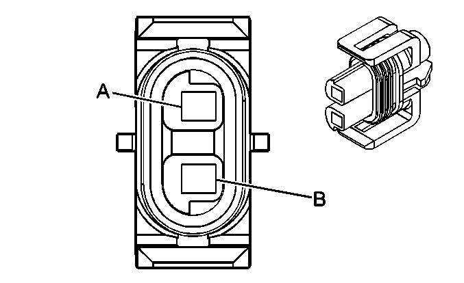
| |||||||
|---|---|---|---|---|---|---|---|
Connector Part Information |
| ||||||
Pin | Wire Color | Circuit No. | Function | ||||
A | BK | 250 | Ground | ||||
B | D-GN | 59 | A/C Compressor Clutch Supply Voltage | ||||
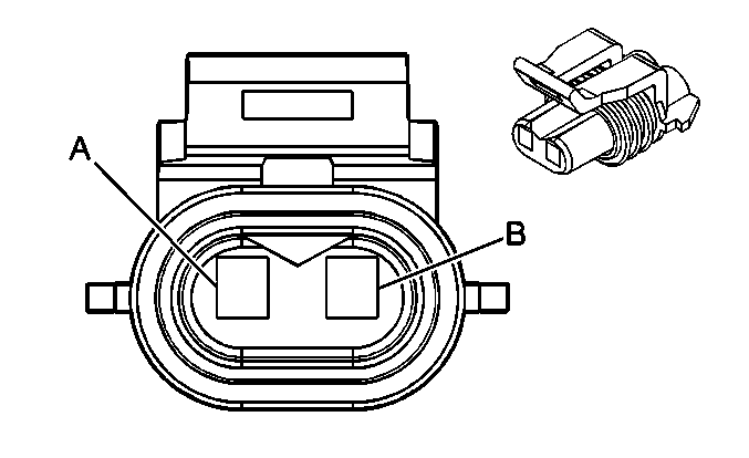
| |||||||
|---|---|---|---|---|---|---|---|
Connector Part Information |
| ||||||
Pin | Wire Color | Circuit No. | Function | ||||
A | BK | 250 | Ground | ||||
B | D-GN | 59 | A/C Compressor Clutch Supply Voltage | ||||
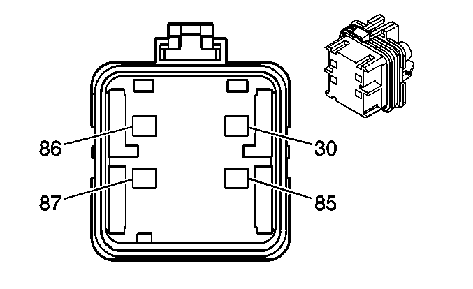
| |||||||
|---|---|---|---|---|---|---|---|
Connector Part Information |
| ||||||
Pin | Wire Color | Circuit No. | Function | ||||
30 | OG | 1240 | Battery Positive Voltage | ||||
85 | D-GN | 603 | Low Coolant Indicator Control (LG4/LG5) | ||||
D-GN/WH | 459 | A/C Compressor Clutch Relay Control (LB7/L18) | |||||
86 | D-GN/WH | 459 | A/C Compressor Clutch Relay Control (LG4/LG5) | ||||
BN | 441 | Ignition 3 Voltage (L18/LB7) | |||||
87 | D-GN | 59 | A/C Compressor Clutch Supply Voltage | ||||
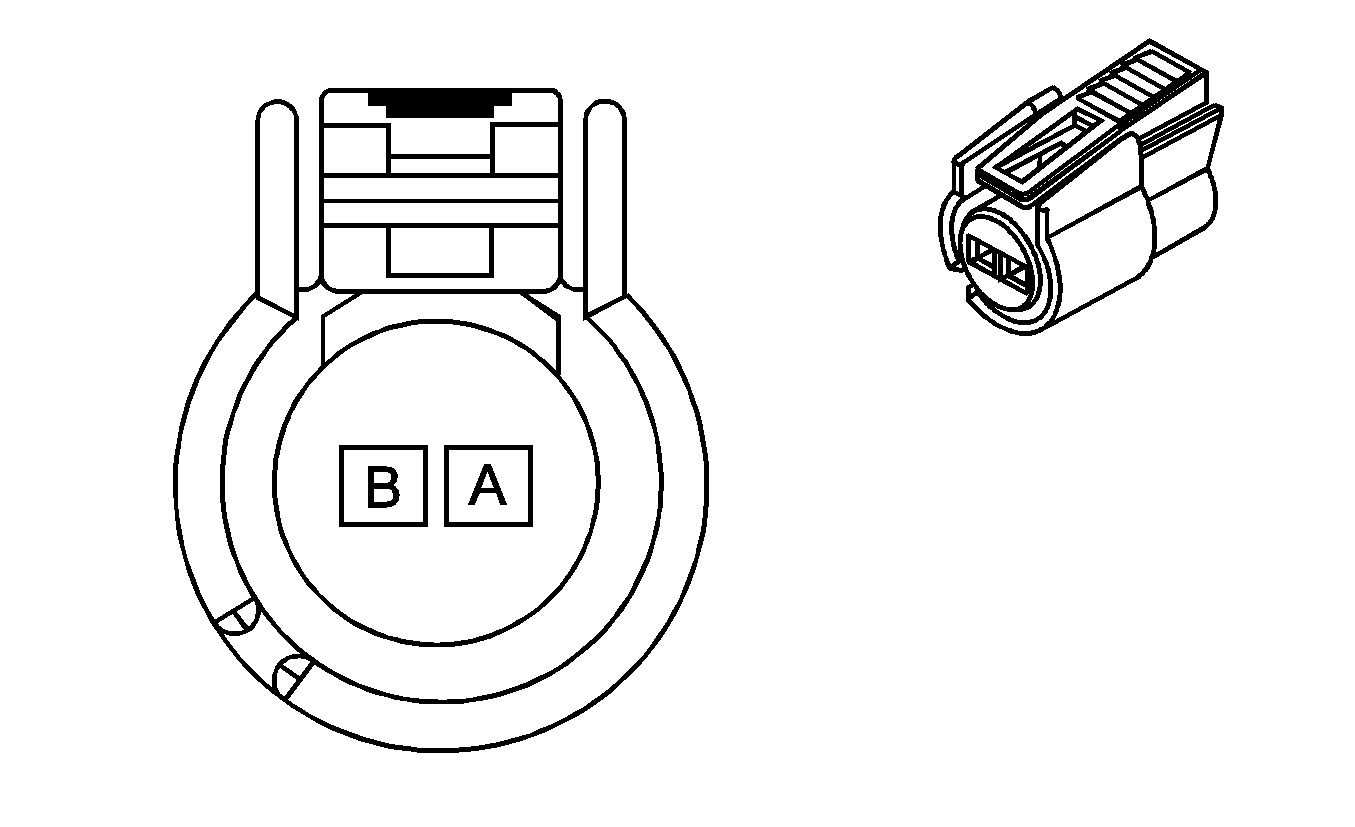
| |||||||
|---|---|---|---|---|---|---|---|
Connector Part Information |
| ||||||
Pin | Wire Color | Circuit Number | Function | ||||
A | D-GN | 762 | A/C Request Signal (L18/LB7) | ||||
L-GN | 66 | A/C Request Signal (LG4/LG5) | |||||
B | L-GN | 66 | A/C Request Signal (L18/LB7) | ||||
D-GN/WH | 459 | A/C Compressor Clutch Relay Control (LG4/LG5) | |||||
| |||||||
|---|---|---|---|---|---|---|---|
Connector Part Information |
| ||||||
Pin | Wire Color | Circuit No. | Function | ||||
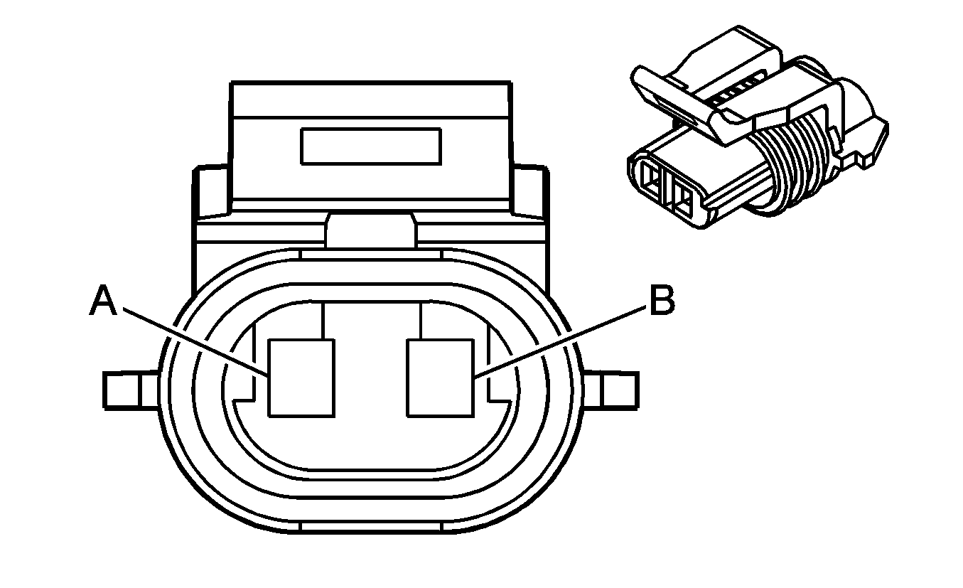
A | BK | 250 | Ground & L18/LB7 | ||||
B | D-GN | 603 | Low Coolant Indicator Control | ||||
| |||||||
|---|---|---|---|---|---|---|---|
Connector Part Information |
| ||||||
Pin | Wire Color | Circuit No. | Function | ||||
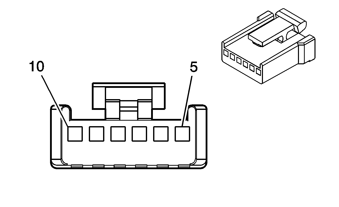
5-6 | -- | -- | Not Used | ||||
7 | BK | 450 | Ground | ||||
8 | L-BU | 733 | Left Air Temperature Door Control | ||||
9 | -- | -- | Not Used | ||||
10 | BN | 141 | Ignition 3 Voltage 7 | ||||
| |||||||
|---|---|---|---|---|---|---|---|
Connector Part Information |
| ||||||
Pin | Wire Color | Circuit Number | Function | ||||
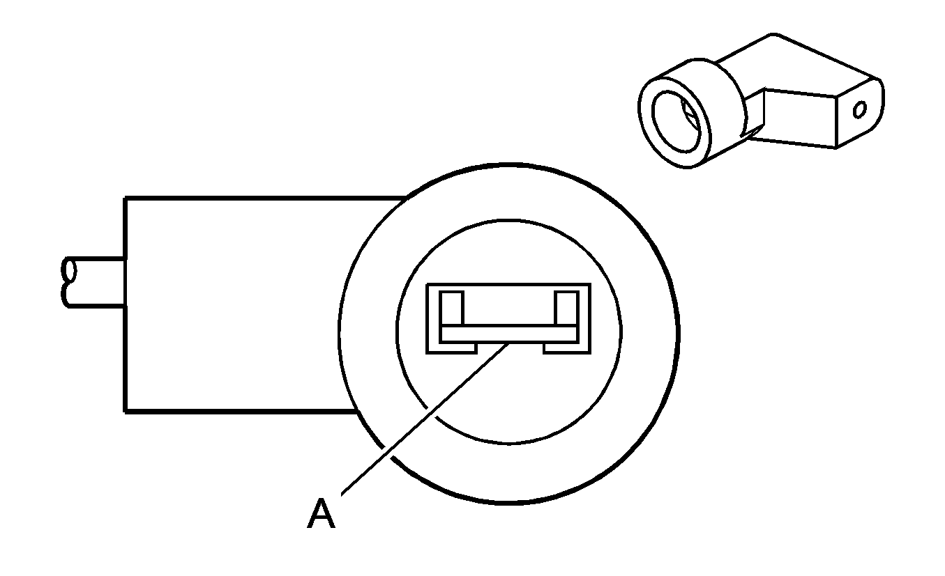
A | YE | 1172 | Auxiliary Blower Motor Supply Voltage | ||||
| |||||||
|---|---|---|---|---|---|---|---|
Connector Part Information |
| ||||||
Pin | Wire Color | Circuit No. | Function | ||||
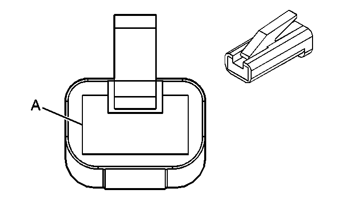
A | BK | 550 | Ground & C36 | ||||

| |||||||
|---|---|---|---|---|---|---|---|
Connector Part Information |
| ||||||
Pin | Wire Color | Circuit No. | Function | ||||
30 | OG | 540 | Battery Positive Voltage & C36 | ||||
85 | BK | 550 | Ground & C36 | ||||
86 | BN | 141 | Ignition 3 Voltage & C36 | ||||
87 | OG | 1923 | Auxiliary HVAC Switch Supply Voltage | ||||
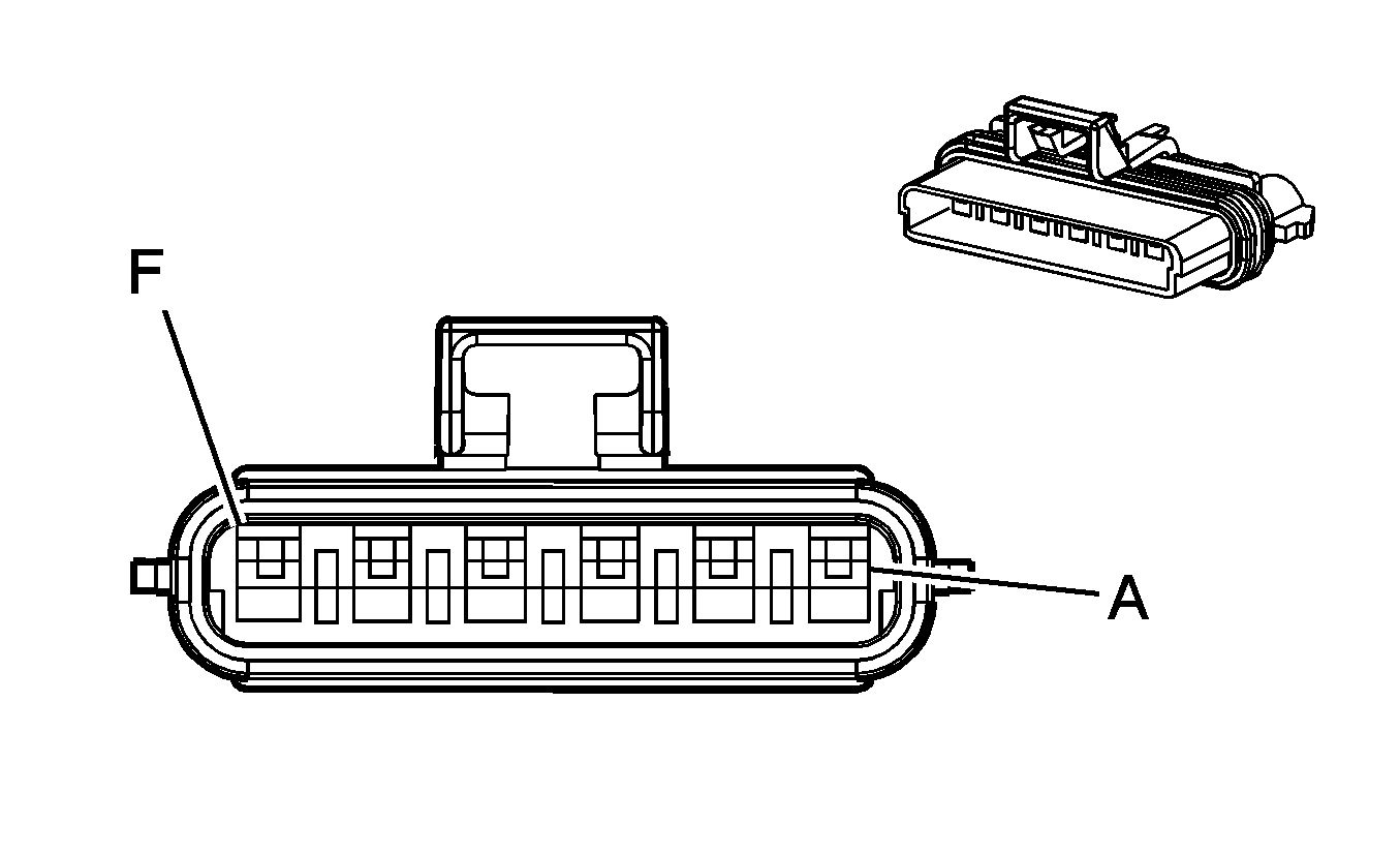
| |||||||
|---|---|---|---|---|---|---|---|
Connector Part Information |
| ||||||
Pin | Wire Color | Circuit No. | Function | ||||
A | RD | 542 | Battery Positive Voltage | ||||
B | OG | 52 | High Blower Motor Control | ||||
C | BK | 450 | Ground | ||||
D | TN | 63 | Auxiliary Blower Motor Medium Speed Control | ||||
E | YE | 60 | Low Blower Motor Control | ||||
F | L-BU | 72 | Medium 2 Blower Motor Control | ||||
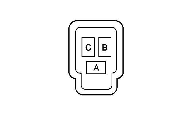
| |||||||
|---|---|---|---|---|---|---|---|
Connector Part Information |
| ||||||
Pin | Wire Color | Circuit No. | Function | ||||
A | RD | 1925 | Auxiliary Blower Motor Medium Speed Control | ||||
B | YE | 1172 | Auxiliary Blower Motor Supply Voltage | ||||
WH | 1924 | Auxiliary Blower Motor High Control | |||||
C | D-BU | 1926 | Auxiliary Blower Motor Low Speed Control | ||||
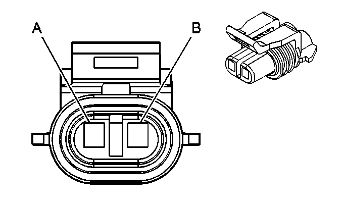
| |||||||
|---|---|---|---|---|---|---|---|
Connector Part Information |
| ||||||
Pin | Wire Color | Circuit No. | Function | ||||
A | GY/BK | 1596 | Heater Water Control Solenoid Control | ||||
B | BK | 550 | Ground | ||||
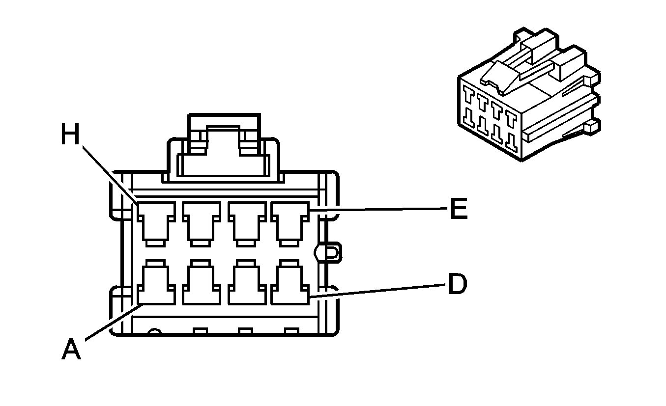
| |||||||
|---|---|---|---|---|---|---|---|
Connector Part Information |
| ||||||
Pin | Wire Color | Circuit No. | Function | ||||
A | WH | 1924 | Auxiliary Blower Motor High Speed Control | ||||
B | RD | 1925 | Auxiliary Blower Motor Medium Speed Control | ||||
C | GY/BK | 1596 | Heater Water Control Solenoid Control | ||||
D | -- | -- | Not Used | ||||
E | BK | 550 | Ground | ||||
F | D-BU | 1926 | Auxiliary Blower Motor Low Speed Control | ||||
G | OG | 1923 | Auxiliary HVAC Switch Supply Voltage | ||||
H | GY | 8 | Instrument Panel Lamp Supply Voltage - 1 | ||||
| |||||||
|---|---|---|---|---|---|---|---|
Connector Part Information |
| ||||||
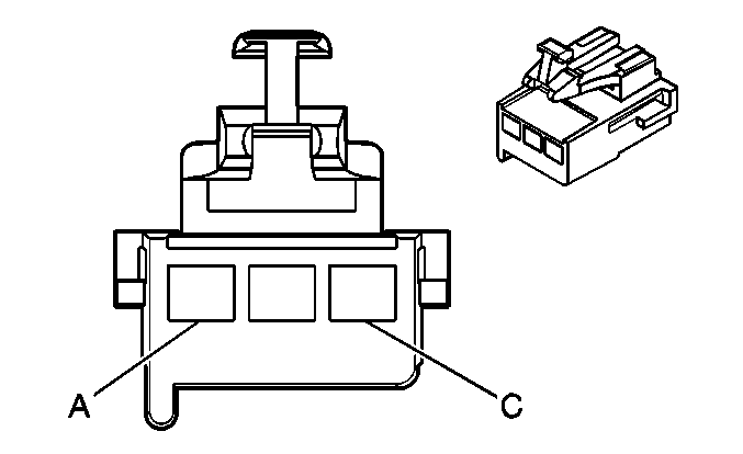
Pin | Wire Color | Circuit No. | Function | ||||
A | WH | 119 | Mode Door Control | ||||
B | BK | 450 | Ground | ||||
C | GY | 8 | Instrument Panel Lamp Supply Voltage - 1 | ||||
| |||||||
|---|---|---|---|---|---|---|---|
Connector Part Information |
| ||||||
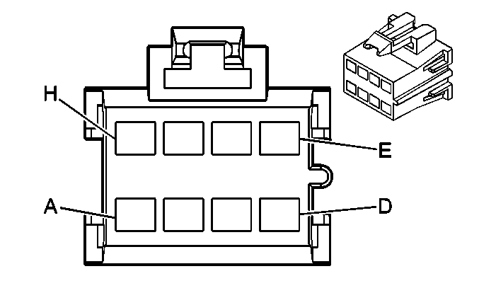
Pin | Wire Color | Circuit No. | Function | ||||
A | YE | 60 | Low Blower Motor Control | ||||
B | TN | 63 | Auxiliary Blower Motor Medium Speed Control 5 | ||||
C | L-BU | 72 | Medium 2 Blower Motor Control | ||||
D | OG | 52 | High Blower Motor Control | ||||
E | BN | 141 | Ignition 3 Voltage | ||||
F | L-BU | 733 | Left Air Temperature Door Control | ||||
G | WH | 119 | Mode Door Control | ||||
H | L-GN | 66 | A/C Request Signal | ||||

| |||||||
|---|---|---|---|---|---|---|---|
Connector Part Information |
| ||||||
Pin | Wire Color | Circuit No. | Function | ||||
A | BK | 350 | Battery Positive Voltage | ||||
B | BN | 141 | Ignition 3 Voltage | ||||
